Sunday, December 29, 2013

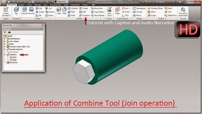
Application of Combine Tool (Join operation) Autodesk Inventor 2013

Application of Combine Tool (Join operation) Autodesk Inventor

Video Tutorial with caption and audio narration

In this video tutorial two pre-constructed parts have been utilized to show Boolean operation in a part file, by using 'Combine' tool that is available in the Modify panel of 3D Model tab.


First of all get the model files required to complete this tutorial by visiting the following link:- http://bit.ly/2oQSwpv 


Transcription of Video

1. We have two files one is Cylinder and the other is Example Insert.
2. Open the Cylinder file.
3. Activate the Derived Component tool.
4. Select the Example Insert file and open it.
5. Click OK to place the Example Insert in the design window.
6. Re-orient the model in the design window by using View Cube.
7. Change the Visual Style to Shaded with Hidden Edges to see the Example Insert clearly.
8. Two separate solid bodies are visible clearly in the Browser Bar.
9. Close the visibility of Cylinder.
10. Activate the Measure Tool from the Marking menu.
11. Take the measurement of this edge.
12. Measurement of the edge is 0.5 inch.
13. Open the visibility of Cylinder.
14. Start the Move Bodies tool.
15. And then select Example Insert.
16. Enter value 0 inch in the X Offset input box.
17. To move the Example Insert in Z direction.
18. Enter value (-0.5) inch in the Z Offset input box and click OK.
19. Activate the Combine tool.
20. Join option is selected by default.
21. Select both the solid bodies in the design window.
22. Click OK to close the dialog box.
23. Now checkout the Browser Bar, only one solid body exists.
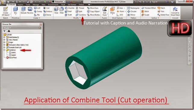
Application of Combine Tool (Cut operation) Autodesk Inventor 2013

Application of Combine Tool (Cut operation)

Video Tutorial with caption and audio narration

In this video tutorial two pre-constructed parts have been utilized to show Boolean operation in a part file, by using 'Combine' tool that is available in the Modify panel of 3D Model tab.


First of all get the model files required to complete this tutorial by visiting the following link:- http://bit.ly/2ClzJpi 


Transcription of Video

1. We have two files one is Cylinder and the other is Example Insert.
2. Open the Cylinder file.
3. Activate the Derived Component tool.
4. Select the Example Insert file and open it.
5. Click OK to place the Example Insert in the design window.
6. Re-orient the model in the design window by using View Cube.
7. Two separate solid bodies are visible clearly in the Browser Bar.
8. Activate the Combine tool.
9. First select Cylinder as a base body.
10. And then select Example Insert as a tool body.
11. Join option is selected by default.
12. Select Cut option to remove the material from Cylinder Part.
13. Click OK to close the dialog box.

Saturday, December 28, 2013

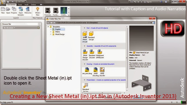
Creating a New Sheet Metal (in).ipt file in Autodesk Inventor 2013

Creating a New Sheet Metal (in).ipt file in Autodesk Inventor 2013

Video Tutorial with caption and audio narration

The main use of this type of template or file is to create a 3D object fabricated from sheet material of uniform thickness that can be unfolded too.


Transcription of Video

1. To create a new Sheet Metal part file, click 'New' icon on the Launch Panel of Get Started Tab.
2. Create New File Dialogue Box is visible.
3. Click English Folder under Templates.
4. Double click the 'Sheet Metal (in).ipt' to open it.
5. Save it with the name 'Square Bend Tube'.

Friday, December 20, 2013

Creation of Exploded View of a Model-Autodesk Inventor 2013 (with caption and audio narration)

Creation of Exploded View of a Model

 Serial No. 125

Creation of Exploded View of a Model-Autodesk Inventor 2013 (with caption and audio narration)


 download-Link 


Click the following link to get the model file: - http://bit.ly/2nskR4s


Transcription of Video

Creation of Exploded View of a Model in a Presentation File (Autodesk Inventor 2013)

  1. Create a new Standard (in).ipn Presentation File.
  2. Click ‘Create View’ icon in the Create panel of Presentation Tab.
  3. In the Select Assembly dialogue box, click ‘Open an existing file’ button under the File section.
  4. Select the ‘Vise’ Assembly and Click Open.
  5. Explosion Method should be selected to ‘Manual’.
  6. Click Ok.
  7. Save the file with the default name.
  8. Click ‘Tweak Components’ tool on the Create panel.
  9. Select front face of Vise to set the Direction.
  10. Select Sub Assembly-3 in the Browser Bar as Component.
  11. Place the cursor in the empty area of Design window and drag the component in Z direction.
  12. Enter the value 40 inch in Tweak Distance input box under the ‘Transformations Section’ to precisely move the component.
  13. Click green check mark to apply.
  14. Hold the Ctrl key and click the Sub Assembly-3 to remove it from the selection.
  15. Select the Sub Assembly-2 in the Browser Bar.
  16. Drag the Component 22 inch away in the Z direction.
  17. Click Close to finish adding tweaks to the exploded view.
  18. Adjust the model in the design window by using Navigation Tools: Zoom and Pan.
  19. Set the Current View as Home view by using the toggle next to View Cube.
  20. Click the ‘Browser Filters’ icon in the Browser Bar.
  21. Select ‘Sequence View’ from the context menu.
  22. Double click the Task1.
  23. In the Edit Task & Sequences dialog box, select ‘Sequence2’ from drop down menu of Sequences.
  24. Click Set Camera button then Apply it.
  25. Click Play Forward button to check the Animation Sequence.
  26. Click Reset to set the Animation back to the beginning.
  27. Now set the camera for the ‘Sequence1’ in the same manner.
  28. Adjust the view of the model by using Navigation Tools.
  29. Set the Camera and click Apply.
  30. Check the Animation Sequence by clicking the Play Forward button.
  31. Click Ok to close the Edit Task & Sequences dialogue box.
  32. Click Animate Tool on the Create panel.
  33. In the Animation dialogue box, fill the value 50 in ‘Interval’ Input box and click Apply.
  34. Click ‘Play Forward’ button to see the animation.
  35. Click Reset button and close the dialogue box.
  36. Now Zoom the window so that Sub Assembly-1 can be seen clearly.
  37. Activate Tweak Component Tool.
  38. Select Front Face of Sub Assembly-1 to set the Direction.
  39. Select both the Screws as component and drag them 4 inch away in Z direction.
  40. Hold the Ctrl key and click both the screws to remove them from the selection.
  41. Select the Jaw Plate and drag it 2 inch away in the Z direction.
  42. Click Clear button, it will clear the settings in the dialog box.
  43. Now it is ready to setup for another tweak.
  44. Click the cylindrical face of Screw to set the direction, select Screw again.
  45. Change the Transformation type from Linear to Rotational by clicking the Rotational Radio Button.
  46. Enter the Transformation value (-720) degree and click the green check mark.
  47. Click Clear Button.
  48. In the same manner create another Tweak for the second screw.
  49. Select cylindrical face of screw then click the screw.
  50. Enter the Transformation Value (-720) degree and click green check mark to apply.
  51. Close the Tweak Component dialogue box.
  52. Expand the Sequence1, 2, 3 and 4 in the Browser Bar to show the Hidden folders.
  53. Select the Sub Assembly-2 and Sub Assembly-3, drag and drop them under all the Hidden Folders visible.
  54. By doing so both the Sub-Assemblies will be hidden, during the Animation of Sequence1, 2, 3 and 4.
  55. Open the Animate Tool.
  56. Click more button to expand the Animation dialogue box.
  57. Click Play Forward Button.
  58. At present both the Screws are rotating separately.
  59. Click Pause Button and Reset the Animation Player.
  60. Select Sequence 1 and Sequence 2 from the Animation Sequence list by holding Ctrl Key.
  61. Click Group Button to combine two tweaks into Sequence1 and Apply it.
  62. Click play button to see the effect.
  63. Click Pause Button and Reset the Animation Player.
  64. Click the Sequence 1 in the Animation Sequence List and click the Move Down button two times.
  65. Now this Sequence will be labeled as Sequence 3.
  66. Click Apply.
  67. Now play the animation to see the effect.
  68. Click Reset Button and close the dialogue box.
  69. Double click the Task1 in Browser Bar to open Edit Task & Sequences dialog box.
  70. Set the Camera for Sequence 1, 2 and 3 as displayed.
  71. Click OK to close the dialogue box.
  72. Adjust the design window with the help of navigation tools, so that the Part-1 of Sub Assembly-1 can be seen clearly.
  73. To do so, take the help of common navigation tools and Precise View rotation Tool.
  74. Activate Tweak Components tool.
  75. Select front face of Vise as Direction.
  76. Then the select Part-1 as Component.
  77. Click Y button in the Linear Transformation type option.
  78. Drag the Part-1 (-0.625) inch away.
  79. Now select Z button in the Linear Transformation type option to move the ‘Part-1’, 8 inch away in Z direction.
  80. Close the Tweak Components dialog box.
  81. Double click the Sequence 2 in the Browser Bar to open Edit Task & Sequences dialog box.
  82. Set Camera for the Sequence 2 and 1.
  83. Close the Edit Task & Sequences dialog box.
  84. Expand the elements of Sequence2 and put the Sub Assembly-2 in its Hidden folder by using drag and drop method.
  85. Re-Adjust the design window using Navigation tools so that Jaw of Sub Assembly-2 can be seen clearly.
  86. Activate the Tweak Component Tool.
  87. Select the front face of Sub Assembly-2 as Direction.
  88. Select both the Screws as Component.
  89. Drag them 4 inch away in Z direction.
  90. Hold the Ctrl key and click both the screws to remove them from the selection.
  91. Select the Jaw Plate and drag it 2 inch away in the Z direction.
  92. Click Clear button, it will clear the settings in the dialog box.
  93. Now it is ready to setup for another tweak.
  94. Click the cylindrical face of Screw to set the direction then select Screw again.
  95. Change the Transformation type from Linear to Rotational by clicking the Rotational Radio Button.
  96. Enter the Transformation value (-720) degree and click the green check mark.
  97. Click Clear Button.
  98. In the same manner create another Tweak for the second screw.
  99. Select cylindrical face of screw then click the screw.
  100. Enter the Transformation Value (-720) degree and click green check mark to apply.
  101. Close the Tweak Component dialogue box.
  102. Open the Animate Tool.
  103. Click more button to expand the Animate dialogue box.
  104. Select Sequence 1 and Sequence 2 from the Animation Sequence list by holding Ctrl Key.
  105. Click Group Button to combine two tweaks into Sequence1 and Apply it.
  106. Click the Sequence 1 in the Animation Sequence List and click the Move Down button two times.
  107. Now this Sequence will be labeled as Sequence 3.
  108. Click Apply.
  109. Now play the animation to see the effect.
  110. Click Pause button and close the dialogue box.
  111. Double click the Task1 in Browser Bar.
  112. Set the Camera for Sequence 1, 2 and 3 as displayed.
  113. Click OK to close the dialogue box.
  114. Re-Adjust the design window using Navigation tools, so that the ‘Pin’ of Sub Assembly-3 can be seen clearly.
  115. Double Click the Pin of Sub Assembly-3 to activate the Tweak Component tool.
  116. Select the top face of Pin to set the direction.
  117. Drag the Pin 3.5 inch away in Z direction.
  118. Click Clear Button.
  119. Select the front face of Washer to set the Direction.
  120. Select the Washer and drag it 2.5 inch away in Z direction.
  121. Hold the Ctrl Key and click the Washer to remove it from the selection.
  122. Now select the Spring and drag it 2 inch away in Z direction.
  123. Click Clear button.
  124. Select the cylindrical face of the Handle to set the Direction.
  125. Select the Handle and drag it (-2.5 inch) away in Z direction.
  126. Close the Tweak Component dialogue box.
  127. Double click the Task1 in Browser Bar.
  128. Set the Camera for Sequence 1, 2, 3 and 4 as displayed.
  129. Click OK to close the dialogue box.
  130. Go to Home View, to readjust the design window.
  131. Activate the Animate tool.
  132. Clear the screen by activating the Clean screen command.
  133. Click ‘Play Forward’ Button to play the Animation.
  134. Click Reset Button to restore the Assembly in Exploded mode.

Monday, December 16, 2013

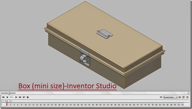
Box (mini size)-Inventor Studio-Autodesk Inventor 2013 (with caption and audio narration)


Box (mini size)-Inventor Studio_1
Box (mini size)-Inventor Studio_2


Serial No. 10

Box (mini size)-Inventor Studio-Autodesk Inventor 2013 (with caption and audio narration)

In this video, we will demonstrate how to give the different type of mates in the assembly environment for creating the animation of the ‘Box (mini size)'.


download-Link 


Click the following link to get the model file:- http://bit.ly/2n4wL4j


 Transcription of Video

Display of motion in Box (mini size) through Inventor Studio

Base Body Assembly:-

  1. Create a New ‘Standard (in).iam’ Assembly file.
  2. Save it with the name ‘Base Assembly’.
  3. Select ‘Place Component’ from the marking menu and place the ‘Base Body’ in the Assembly.
  4. Re-orient the model in the design window by using View Cube.
  5. Set the current view as Home View by using the toggle next to View Cube.
  6. Place the ‘Hook of Latch’ in the Assembly.
  7. Align the Hook of Latch with reference to box, by using the Rotate Component Tool.
  8. Apply a Mate Constraint between front face of Base Body and back face of Hook of Latch.
  9. Apply a Flush Mate between YZ plane of Assembly and XY plane of Hook of Latch.
  10. Apply another Flush Mate between top face of Base of Box and top face of Hook of Latch.
  11. Enter the value (-0.688) inch in the Offset input box.
  12. Place the ‘Hinge’ in the Assembly.
  13. Align the Hinge with reference to box, by using the Rotate Component Tool.
  14. Apply an Axis Mate between round rim of Base Body and Hinge.
  15. Apply a Mate Constraint between Red face of Hinge and back face of Base Body.
  16. Apply a Flush Mate between side face of Base Body and side face of Hinge.
  17. Enter the value (-2.5 inch) in the Offset input box.
  18. Hold the Ctrl Key and select Hinge in Browse Bar.
  19. Drag the Hinge in design window to place another identical part in the Assembly.
  20. Repeat the same process to fix the second Hinge on the Base Body.
  21. Align the Hinge with reference to Box, by using the Rotate Component Tool.
  22. Apply an Axis Mate between round rim of Base Body and Hinge.
  23. Apply a Mate Constraint between Red face of Hinge and back face of Base Body.
  24. Apply a Flush Mate between side face of Base Body and side face of Hinge.
  25. Enter the value (-2.5 inch) in the Offset input box.
  26. Save the Assembly and close it.

Lid Assembly:-

  1. Create a New ‘Standard (in).iam’ Assembly.
  2. Save it with the name ‘Lid Assembly’.
  3. Select ‘Place Component’ from the marking menu and place the ‘Lid’ in the Assembly.
  4. Place the ‘Wire’ in the Assembly.
  5. Apply an Axis Mate between the Wire and front round rim of Lid.
  6. Apply an Axis Mate between the Wire and side rim of Lid.
  7. Place the ‘Top of Latch’ in the Assembly.
  8. Apply an axis Mate between Wire and Top of Latch.
  9. Apply a Mate Constraint between green face of Lid and Top of Latch.
  10. Re-orient the model in the design window by using View Cube.
  11. Set the current view as Home View by using the toggle next to View Cube.
  12. Apply Angle Constraint, first select front face of Lid then select front face of Top of Latch and at the last select side face of Lid.
  13. Click Ok.
  14. Place the ‘Handle Base’ in the Assembly.
  15. Apply a Mate Constraint between back face of Handle Base and Top face of Lid.
  16. Apply a Mate Constraint between YZ Plane of Assembly and XY Plane of Handle Base.
  17. Apply a Mate Constraint between XY Plane of Assembly and YZ Plane of Handle Base.
  18. Place the ‘Handle Wire’ in the Assembly.
  19. Apply an Axis Mate between Axis of Handle Wire and ‘Work Axis1’ of Handle Base in the Browser Bar.
  20. Apply a Mate Constraint between XY Plane of Assembly and YZ Plane of Handle Wire.
  21. Activate Angle Constraint, first select YZ Plane of Assembly then select XY Plane of Handle Wire and at the last select side face of Lid.
  22. Enter the value 66.02 degree in the Angle Input Box.
  23. Click Ok.
  24. Set the browser from Assembly View to Modeling View by using Toggle at the top of the Browser Bar.
  25. Select the Angle:2 Constraint under the Constraints folder in the Browser Bar and Change its name as ‘Drive-1’ by clicking twice slowly.
  26. In the same manner, change the name of the Angle:1 constraint as ‘Drive-2’.
  27. Save the Assembly and close it.

Main Assembly:-

  1. Create a New ‘Standard (in).iam’ Assembly.
  2. Save it with the name ‘Box (mini size)-Inventor Studio’.
  3. Select ‘Place Component’ from the marking menu and place the ‘Base Assembly’ in the Main Assembly.
  4. Re-orient the model in the design window by using View Cube.
  5. Set the current view as Home View by using the toggle next to View Cube.
  6. Place the ‘Lid Assembly’ in the Main Assembly.
  7. Align the Lid Assembly with reference to Base Assembly, by using the Rotate Component Tool.
  8. Apply an Axis Mate between Axis of Wire and Axis of Hinge.
  9. Apply a Mate Constraint between current selected face (yellow coloured) of Lid and current selected face (yellow coloured) of Hinge.
  10. Activate Angle Constraint, first select front face of Base then select front face of Lid and at the last side face of Base.
  11. Click OK.
  12. Select the Angle:1 Constraint under the Base Assembly in the Browser Bar and Change its name as ‘Drive-3’ by clicking twice slowly.
  13. Click the ‘Inventor Studio’ icon from the Begin Panel of Environments Tab.
  14. Click the ‘Animation Timeline’ icon from the Animate Panel of Render Tab.
  15. Click the Animation Options Button on the Animation Timeline.
  16. In the Animation Options dialogue box, enter the value 1 minute 35 seconds in the ‘Length’ section option.
  17. Select Constant Speed radio button in the Default Velocity Profile and click Ok.
  18. Select ‘Drive-1’ Constraint under Handle Wire:1 in the Browser Bar, right click and select Animate Constraints in the context menu.
  19. In ‘Action’ section of Animate Constraint dialogue box, enter the value (-66.02) degree in the End input box.
  20. In the ‘Time’ section of Animate Constraint dialogue box, click Specify Button and enter the value 15 second in the End input box.
  21. Click Acceleration Tab.
  22. Select ‘Constant Speed’ radio button in the Velocity Profile.
  23. Click OK.
  24. Click Expand Action Editor Button on the Animation Timeline.
  25. Select ‘Drive-1’ constraint in the Animation Timeline, right click and choose ‘Mirror’ from the context menu.
  26. Edit previously Mirror animation action in the Animation Timeline.
  27. In the ‘Time’ section of Animate Constraint dialogue box, enter the value 80 second in the Start input box, and enter the value 95 second in the End input box.
  28. Click OK.
  29. Select ‘Drive-2’ Constraint under Top of Latch:1 in the Browser Bar, right click and select Animate Constraints in the context menu.
  30. In ‘Action’ section of Animate Constraint dialogue box, enter the value (-90 degree) in the End input box.
  31. In the ‘Time’ section of Animate Constraint dialogue box, click Specify button.
  32. In the Start input box, enter the value 15 second and in the End input box, enter the value 30 second.
  33. Click Acceleration Tab.
  34. Select ‘Constant Speed’ radio button in the Velocity Profile.
  35. Click OK.
  36. Select ‘Drive-2’ constraint in the Animation Timeline, right click and choose ‘Mirror’ from the context menu.
  37. Edit previously Mirror animation action in the Animation Timeline.
  38. In the ‘Time’ section of Animate Constraint dialogue box, enter the value 65 second in the Start input box and enter the value 80 second in the End input box.
  39. Click OK.
  40. Select ‘Drive-3’ Constraint under Base Assembly:1 in the Browser Bar, right click and select Animate Constraints in the context menu.
  41. In ‘Action’ section of Animate Constraint dialogue box, enter the value (-90 degree) in the End input box.
  42. In the ‘Time’ section of Animate Constraint dialogue box, click Specify button.
  43. In the Start input box, enter the value 30 second and in the End input box, enter the value 45 second.
  44. Click Acceleration Tab.
  45. Select ‘Constant Speed’ radio button in the Velocity Profile.
  46. Click OK.
  47. Select ‘Drive-3’ constraint in the Animation Timeline, right click and choose ‘Mirror’ from the context menu.
  48. Edit previously Mirror animation action in the Animation Timeline.
  49. In the ‘Time’ section of Animate Constraint dialogue box, enter the value 50 second in the Start input box and enter the value 65 second in the End input box.
  50. Click OK.
  51. Select Collapse Action Editor Button on the Animation Timeline.
  52. Clear the screen by activating the Clean Screen command.
  53. Click ‘Go to Start’ Button.
  54. Click Play Animation button to display motion in Box (mini size).

Saturday, December 14, 2013

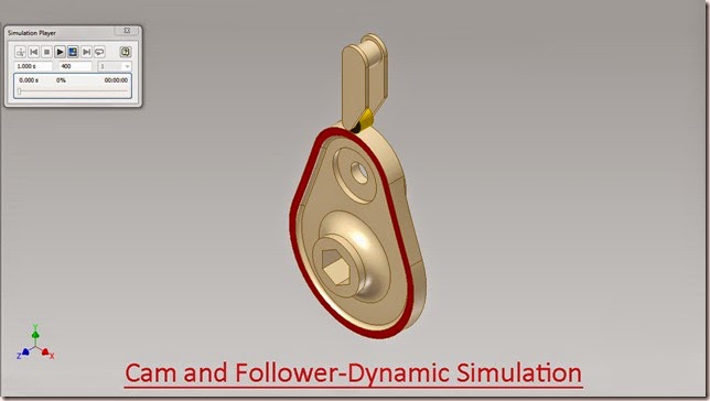
Cam and Follower-Dynamic Simulation-Autodesk Inventor 2013 (with caption and audio narration)

Cam and Follower-Dynamic Simulation

Serial No. 183

Cam and Follower-Dynamic Simulation-Autodesk Inventor 2013 (with caption and audio narration)
In this video, we will demonstrate how to apply the different type of mates in the assembly environment for creating the Dynamic Simulation of the ‘Cam and Follower’. 

download-Link 


Click the following link to get the model file : - http://bit.ly/2maTL1C


Transcription of Video

Display of motion in ‘Cam and Follower’ through Dynamic Simulation

  1. Click the New icon under the Work tab in the Welcome Screen of Autodesk Inventor Professional 2013.
  2. Select Metric Template in the Create New File Dialogue Box.
  3. Create a Standard (mm).iam Assembly file.
  4. Save it with the name ‘Cam and Follower-Dynamic Simulation’.
  5. Select Place component from the marking menu and place the ‘Cam’ in the Assembly.
  6. Align the Cam in correct position by using View Cube.
  7. Set the current view as Home View by using the toggle next to View Cube.
  8. Select the Cam in the design window and remove its ‘Grounded’ position from the context menu.
  9. Click the Degrees of Freedom icon in the Visibility Panel of View Tab.
  10. At present there are six Degrees of Freedom in Cam and it can be moved in any direction in the Assembly.
  11. Apply an Axis Mate between the Z Axis of Assembly and Z Axis of Cam.
  12. Apply a Flush Mate between the XY Plane of Assembly and upper most front face (Red coloured) of Cam.
  13. Now this time only one ‘Degrees of Freedom’ persist and Cam can be moved only on its Z Axis.
  14. Place the ‘Follower’ in the Assembly.
  15. Re-orient the Follower against the Cam using Rotate Component Tool.
  16. Apply a Flush Mate between the upper most front face (Red coloured) of Cam and face of small pulley (Black coloured) of Follower.
  17. Apply a Mate Constraint between YZ Plane of Assembly and YZ Plane of Follower.
  18. Activate the Dynamic Simulation Tool from the Begin Panel of Environments Tab.
  19. Click the view Tab and change the View of the model to ‘Shaded with Edges’ in the Visual Style drop down.
  20. Activate Insert Joint from the Marking menu.
  21. Select ‘Sliding: Cylinder Curve’ from the drop down menu of Insert Joint dialog box.
  22. Select the outer edge of Cam in ‘Curve’ selection option and select circular edge of small pulley of Follower in ‘Cylinder’ selection option.
  23. Click OK.
  24. Select Revolution:1 joint in the Browser under the Standard Joints folder, right click and select Properties from the context menu.
  25. Click dof 1 (R) tab and select Edit imposed motion button and check the Enable imposed motion option.
  26. Click the arrow to expand the input choices, and click Constant Value.
  27. Enter the value 360*2 deg/s and click Ok.
  28. In Simulation Player fill the value 400 in the Images field area.
  29. Clear the screen by activating the Clean Screen command.
  30. Click Run in the Simulation Player to display motion in Cam and Follower.

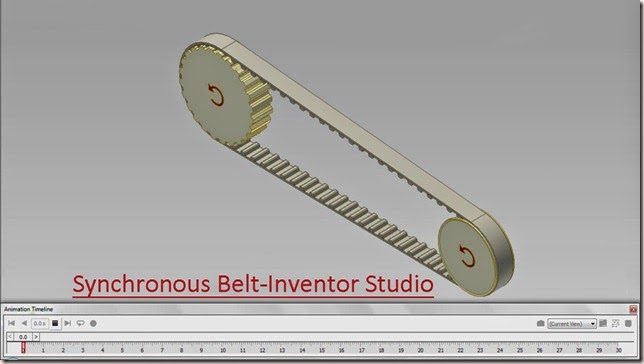
Synchronous Belt-Inventor Studio-Autodesk Inventor 2012 (with caption and audio narration)

Synchronous Belt-Inventor Studio

Serial No. 94

Synchronous Belt-Inventor Studio-Autodesk Inventor 2012 (with caption and audio narration)

In this video, we will demonstrate how to apply the different type of mates in the assembly environment for creating the animation of the ‘Synchronous Belt’.

download-Link 


Click the following link to get the model file: - http://bit.ly/2mC9Z3Z


Transcription of Video

Display of motion in ‘Synchronous Belt-Inventor Studio’ through Inventor Studio

  1. Create a New ‘Standard (mm) .ipt’ Part file.
  2. At present Sketch1 is active by default.
  3. Use the Finish Sketch command to exit from sketching mode.
  4. Open the visibility of YZ Work Plane under the origin folder in the Browser Bar.
  5. Create a new Work Plane Parallel to YZ Plane at an offset distance of 323.623 mm.
  6. Create a new Sketch on XY Plane.
  7. Draw a Circle of 97.021 mm diameter, coincident with the auto projected part origin.
  8. Create another Circle of 72.766 mm diameter. The distance between these two circles is 323.623 mm.
  9. Take the project of X Axis and convert it to construction geometry.
  10. The centre of small circle is 12.128 mm below the projected X Axis line.
  11. Draw a line connecting top of two circles as displayed.
  12. Take the project of YZ Plane and convert it to construction geometry.
  13. Draw another line between two circles.
  14. Erase the unwanted sketches by using the Trim tool.
  15. Apply dimensions to fully constraint the sketch as displayed.
  16. Take the project of Work Plane1 from the browser bar, with use of Project Geometry tool.
  17. Convert this line into construction geometry.
  18. Apply a dimension between these two projected lines. This dimension is driven dimension.
  19. Now the sketch is complete, exit the sketch environment.
  20. Create a Work Point at the intersection of YZ Plane and bottom line of the sketch.
  21. Activate the Parameters tool from the Parameters Panel of the Manage tab.
  22. Create a User defined Parameter named ‘start’ by clicking ‘Add Numeric’ button in the Parameters dialog box.
  23. Click the ‘Equation’ column and then select the driven dimension in the design window.
  24. Click Done.
  25. Save the Part file with the name ‘Locus of Tooth’.
  26. Start the Rectangular Pattern Tool and select Work Point1 in the Browser Bar as feature.
  27. Click the ‘Direction 1’ button and select the sketch in the design window.
  28. In the Column spacing input box, click arrow button to expand choices.
  29. Select List Parameters then select the ‘start’.
  30. Click more button to expand the dialogue box.
  31. Select Adjust in the ‘Compute’ option.
  32. Click the Start button in the ‘Direction 1’ field and select the Work Point1 in the Browser Bar.
  33. Click OK.
  34. Open the visibility of Sketch2 from the Browser Bar.
  35. Select Work Plane1 in the Browser Bar and make it ‘Adaptive’ from the context menu.
  36. Activate Rectangular Pattern Tool once again.
  37. Select Work Point2 in the Browser Bar as feature.
  38. Click the ‘Direction 1’ button and select the sketch in the design window.
  39. In the Column Count input box, enter the value 72.
  40. Click this drop down to specify pattern length.
  41. Select ‘Curve Length’ option.
  42. Click the more button to expand the dialogue box.
  43. Select Adjust in the ‘Compute’ option.
  44. Click the Start button in the ‘Direction 1’ field and select the Work Point2.
  45. Select Direction1 in the ‘Orientation’ option.
  46. Click OK.
  47. Save the file and close it.
  48. Create a ‘‘Standard (mm) .iam’ assembly’ and save it with the name ‘Synchronous Belt -Inventor Studio’.
  49. Select ‘Place component’ tool from the marking menu and place the ‘Locus of Tooth’ Part in the Assembly.
  50. Select the ‘Locus of Tooth’ Sketch from the Browser Bar, right click and deselect Grounded from the context menu.
  51. Select the ‘Locus of Tooth’ Sketch again and make it ‘Adaptive’ from the context menu.
  52. Align the model in appropriate position using the View Cube.
  53. Apply a Flush Mate between YZ Plane of Assembly and YZ Plane of Locus of Tooth.
  54. Apply a Flush Mate between XZ Plane of Assembly and XZ Plane of Locus of Tooth.
  55. Apply a Flush Mate between XY Plane of Assembly and XY Plane of Locus of Tooth.
  56. Apply a Mate Constraint between YZ Plane of Assembly and Work Plane1 of Locus of Tooth.
  57. Inter the value 323.623 mm in the Offset input box.
  58. Click OK.
  59. Select ‘Place component’ tool from the marking menu and place the ‘Tooth’ part in the Assembly.
  60. Set the browser from Assembly View to Modeling View using the toggle at the top of the browser.
  61. Apply a Mate Constraint between Work Point2 of ‘Tooth’ and Work Point2 of ‘Locus of Tooth’.
  62. Change the view of design window by using View Cube.
  63. Apply a Flush Mate between XY Plane of Assembly and XY Plane of ‘Tooth’.
  64. Apply an Angle Constraint between XZ Plane of Assembly and XZ Plane of ‘Tooth’.
  65. Select Directed Angle option in the solution field.
  66. Close the visibility of Work Planes, visible in the design window.
  67. Create a Work Axis in the Assembly on this point, parallel to Z Axis of the Assembly.
  68. Place the ‘Belt-Base’ in the Assembly.
  69. Apply a Mate Constraint between Z Axis of Assembly and Z Axis of Belt-Base.
  70. Apply an Axis Mate between Belt-Base and Work Axis1 of Assembly.
  71. Apply a Mate Constraint between XY Plane of Assembly and XY Plane of Belt-Base.
  72. Start the Pattern Component Tool from the Component Panel of Assemble tab.
  73. Select the ‘Tooth’ as component, then select Rectangular Pattern2 of Locus of Tooth in the Browser Bar as Associative Feature Pattern.
  74. Click OK.
  75. Now all the ‘Teeth’ are fitted on the Locus of Teeth.
  76. Select ‘Place component’ from the marking menu and place the ‘Small Pulley’ in the Assembly.
  77. Apply a Mate Constraint between Z Axis of ‘Small Pulley’ and Work Axis1 of the Assembly.
  78. Apply a Mate Constraint between XY Plane of ‘Small Pulley’ and XY Plane of the Assembly.
  79. Select ‘Place component’ from the marking menu and place the ‘Large Pulley’ in the Assembly.
  80. Apply a Mate Constraint between Z Axis of ‘Large Pulley’ and Z Axis of the Assembly.
  81. Apply a Mate Constraint between XY Plane of Assembly and XY Plane of the ‘Large Pulley’.
  82. Change the view of design window by using View Cube.
  83. Activate Motion Constraint Command, first select Z Axis of ‘Large Pulley’ and then select Z Axis of ‘Small- Pulley’. Click OK.
  84. Apply an Angle Constraint between XZ Plane of Assembly and XZ Plane of ‘Small Pulley’.
  85. Select Directed Angle option in the solution field.
  86. Change the name of Mate:1 constraint to ‘Drive-1’, and Angle:3 constraint to ‘Drive-2’ in the Browser Bar.
  87. Click the ‘Inventor Studio’ icon from the Begin Panel of Environments Tab.
  88. Select Drive-1 Constraint of Locus of Tooth in the Browser Bar, right click and select Animate Constraints in the context menu.
  89. In the ‘Time’ section of Animate Constraint dialogue box, enter the value 30 second in the End input box.
  90. In ‘Action’ section, enter the value 1 mm in the End input box.
  91. Click Acceleration Tab.
  92. Select Constant Speed radio button in the Velocity Profile.
  93. Click OK.
  94. Select Expand Action Editor Button on the Animation Timeline.
  95. Select Drive-2 Angle Constraint of Small-Pulley in the Browser Bar, right click and select Animate Constraints in the context menu.
  96. In the ‘Action’ section of Animate Constraint dialogue box, enter the value (-360 degree) in the End input box.
  97. In the ‘Time’ section, click the Specify Start Time button.
  98. Click Acceleration Tab.
  99. Select Constant Speed radio button in the Velocity Profile.
  100. Click OK.
  101. Select Collapse Action Editor Button on the Animation Timeline.
  102. Click the Animation Options Button.
  103. In the Animation Options dialogue box, select Constant Speed radio button in the Default Velocity Profile.
  104. Click Ok.
  105. Close the visibility of all the Sketches and Work features.
  106. Clear the screen by activating the Clean Screen command.
  107. Click ‘Go to Start’ Button.
  108. Click Play Animation button.

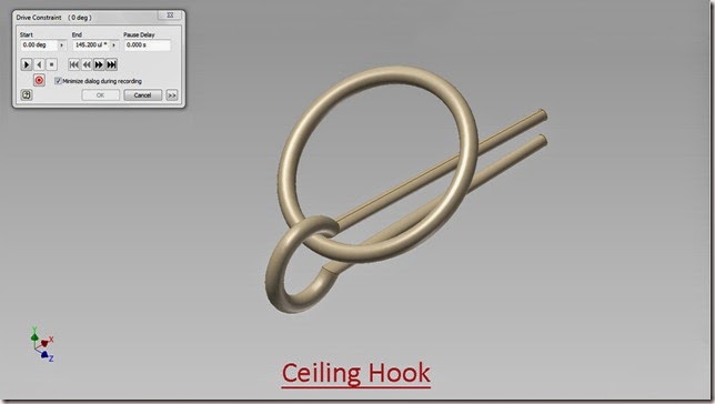
Ceiling Hook-Autodesk Inventor 2013 (with caption and audio narration)


Ceiling Hook
 

Serial No. 16

Ceiling Hook-Autodesk Inventor 2013 (with caption and audio narration) 

download-Link 


Click the following link to get the model file: - http://bit.ly/2mcyc0m


Transcription of Video

Ceiling Hook: -- Modelling and apply motion in it through Drive Constraint

  1. Create a New ‘Standard (in).ipt’ Part file.
  2. Create a new sketch on XY Plane of Part.
  3. Draw a Circle of 0.43800 inch diameter, coincident with Auto projected part origin.
  4. Draw a Line of length 0.25 inch parallel to Y axis.
  5. The midpoint of this line should lie on the X axis.
  6. Apply a Coincident Constraint between the end point of the line and the periphery of the circle.
  7. Create a new Line by taking the offset of this chord.
  8. Give the dimension of 0.15625 inch on this line.
  9. This line should be 1.5 inch away from the chord and its midpoint should lie on X axis.
  10. Start Line tool and join both the ends of this line with the end points of chord of circle.
  11. Convert all the sketches into construction geometry.
  12. Start the Centre Point Arc tool.
  13. Select the Auto projected part origin first then the end points of chord of the circle.
  14. Finish the sketch by clicking the Finish Sketch Icon.
  15. Create a new sketch on XZ plane.
  16. Take the project of last drawn arc and convert it to construction geometry.
  17. Create a circle of .094 inch diameter on the end point of this projected line.
  18. Finish the sketch.
  19. Activate Sweep Tool from the Create Panel of Model Tab.
  20. It will automatically select the small circle created on the Sketch2 as Profile and arc drawn on Sketch1 as path.
  21. Click OK.
  22. Change the Model colour to Flaked Reflective-Beige.
  23. Save the Part file with the name ‘Hook’.
  24. Open the visibility of Sketch1 in Browser Bar.
  25. Create a new Work Plane on this point parallel to YZ Plane of the Part.
  26. Draw a sketch on this work plan.
  27. Take the project of end point of the vertical line.
  28. Draw a Circle of 0.0625 inch diameter.
  29. Finish the sketch.
  30. Start Loft Tool, select small circle and circular edge of the part.
  31. Click OK.
  32. Close the visibility of Sketch1 and Work Plane1.
  33. Start Mirror tool from the Pattern panel of Model Tab.
  34. Select Loft1 from the Browser Bar as feature.
  35. Select XZ Plane from the Browser Bar as Mirror Plane.
  36. Click OK.
  37. Save the file and close it.
  38. Create a New ‘Standard (in).ipt’ Part file.
  39. Create a new sketch on XY Plane of Part.
  40. Draw a Circle of 1 inch diameter, coincident with Auto projected part origin.
  41. Finish the sketch by clicking the Finish Sketch Icon.
  42. Create a new sketch on XZ plane.
  43. Take the Project of big circle and convert it to construction geometry.
  44. Create a circle of 0.094 inch diameter on the end point of this projected line.
  45. Finish the sketch.
  46. Start Sweep Tool, select small circle as profile and select big circle as path.
  47. Click OK.
  48. Change the Model colour to Flaked Reflective-Beige.
  49. Save the file with the name ‘Circular Ring’ and close it.
  50. Create a New ‘Standard (in).iam’ Assembly and Save it with the name ‘Ceiling Hook’.
  51. Select Place Component from the marking menu and place the ‘Hook’ in the Assembly.
  52. Place ‘Circular Ring’ in the Assembly.
  53. Align the Circular Ring according to Hook by using Rotate Component Tool.
  54. Apply a Tangent Mate between Circular Ring and Hook.
  55. Apply a Mate Constraint between XY Plane of Assembly and YZ Plane of Circular Ring.
  56. Edit the Circular Ring in the Assembly by double clicking it.
  57. Activate Work Axis Command.
  58. First select the Centre Point of Hook, then the Z Axis of Hook from the Browser Bar.
  59. In this way a new Work Axis which is Adaptive to Z Axis of Hook is created.
  60. Return to Assembly by clicking Return Icon.
  61. Suppress the Tangent Mate from the Browser Bar, which was applied earlier.
  62. Now the Circular Ring is ready to move along the Hook.
  63. Create an Axis in the Assembly on the basis of two points on the periphery of Hook as displayed.
  64. Go to Work Features panel and click the drop down of Work Plane command.
  65. Select ‘Angle to Plane around Edge’ command.
  66. First select XY Plane of Assembly, then select Work Axis1 of Assembly.
  67. Click OK.
  68. Activate an Angle Constraint, first select Work Plane1 of the Assembly, then select XY Plane of Circular Ring and at last select XY Plane of Assembly.
  69. Click OK.
  70. Open the visibility of XZ Plane of Assembly.
  71. Measure the Angle between XZ Plane of Assembly and Work Plane1 of Assembly.
  72. The magnitude of this angle is 145.2 degree.
  73. Click the Selection drop drown menu and choose ‘Select Sketch Features’ command in the Quick Access Toolbar.
  74. Close the visibility of unnecessary work planes and work axis.
  75. Set the browser from Assembly View to Modeling View by using the Toggle at the top of the Browser Bar.
  76. Select the Angle:2 constraint under the Constraints folder in the Browser Bar and Change its name as ‘Drive’ by clicking twice slowly.
  77. Right click the ‘Drive’ Constraint and select ‘Drive Constraint’ Tool from the context menu.
  78. In the Drive Constraint dialog box, set the End value to (145.2*2) degree.
  79. Click the more button to expand the dialog box, enter the value 0.5 degree in the ‘Increment’ field.
  80. Clear the screen by activating the Clean Screen command.
  81. Click the Forward Button to display motion in ‘Ceiling Hook’.
  82. Click Reverse Button to return at previous position.

Tuesday, December 10, 2013

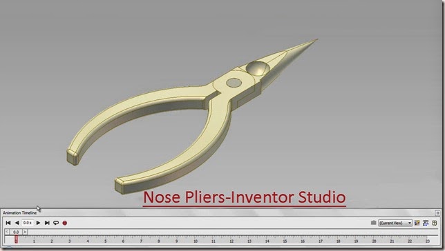
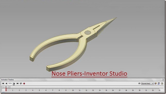
Nose Pliers-Inventor Studio-Autodesk Inventor 2012 (with caption and audio narration)

Nose Pliers-Inventor Studio_1 


Nose Pliers-Inventor Studio_2

Serial No. 66

Nose Pliers-Inventor Studio-Autodesk Inventor 2012 (with caption and audio narration)

In this video, we will demonstrate how to apply the different type of mates in the assembly environment for creating the animation of the ‘Nose Pliers’.

download-Link 


Click the following link to get the model file: - http://bit.ly/2mgIw7T


Transcription of Video

Display of motion in ‘Nose Pliers’ through Inventor Studio

  1. Create a New ‘Standard (in).iam’ Assembly and save it with the name ‘Nose Pliers-Inventor Studio’.
  2. Select Place component from the marking menu and place the ‘Part1’ in the Assembly.
  3. Re-orient the model in the design window by using View Cube.
  4. Set the current view as Home View by using the toggle next to View Cube.
  5. Select the Part1 in the design window and remove its ‘Grounded’ position from the context menu.
  6. Apply an Axis Mate between Z Axis of Assembly and hole of Part1.
  7. Apply a Mate Constraint between XY Plane of Assembly and slotted face of Part1.
  8. Place the ‘Part2’ in the Assembly.
  9. Select the edge of small hole on Part2 to activate Assemble Tool.
  10. Then select the edge of small hole on Part1, click green check mark to place Insert Mate between Part2 and Part1.
  11. Activate an Angle Constraint, first Select face of Jaw of Part1, and then select YZ Plane of Assembly and in the end select top face of Part1. Click OK.
  12. Activate Angle Constraint once again, first Select face of Jaw of Part2, and then select YZ Plane of Assembly and in the end select top face of Part2.
  13. Enter the value 180 degree in the Angle Input box and Click Ok.
  14. Place the ‘Rivet’ in the Assembly.
  15. Select the inner circular edge of Rivet to activate Assemble Tool.
  16. Then select the inner small circular edge of hole on the Part2, click green check mark to place Insert Mate between Part2 and Rivet.
  17. Set the browser from Assembly View to Modeling View using the toggle at the top of the browser.
  18. Select ‘Angle:2’ constraint under the Constraints folder in the Browser Bar, Right click and choose ‘Suppress’ from the context menu.
  19. Select Part1 and Part2 in the Browser Bar, right click and choose ‘Contact Set’ from the context menu.
  20. Select ‘Activate Contact Solver’ in the Interference panel of Inspect Tab.
  21. Drag the Part2, it will stop at the point of Collision between Part1 and Part2.
  22. Measure the swing angle between the jaw of Part1 and Part2. The detected swing angle is 70.64 degree.
  23. Restore the settings to previous state.
  24. Click the ‘Inventor Studio’ icon from the Begin Panel of Environments Tab.
  25. Select ‘Angle:1’ Constraint under Part1 in the Browser Bar, right click and select Animate Constraints in the context menu.
  26. In ‘Action’ section of Animate Constraints dialogue box, enter the value 35.32 degree in the End input box.
  27. In the ‘Time’ section of Animate Constraint dialogue box, enter the value 10 second in the End input box.
  28. Click Acceleration Tab.
  29. Select ‘Constant Speed’ radio button in the Velocity Profile.
  30. Click OK.
  31. Select Expand Action Editor Button on the Animation Timeline.
  32. Select Angle:1 constraint in the Animation Timeline, right click and choose ‘Mirror’ from the context menu.
  33. Edit Mirrored animation action in the Animation Timeline.
  34. In the ‘Time’ section of Animate Constraint dialogue box, enter the value 13 second in the Start input box and enter the value 23 second in the End input box, to give effect of 3 second pause.
  35. Click OK.
  36. Select ‘Angle:2’ Constraint under Part2 in the Browser Bar, right click and select Animate Constraints in the context menu.
  37. In ‘Action’ section, enter the value (180-35.32) degree in the End input box.
  38. In the ‘Time’ section of Animate Constraint dialogue box, enter the value 10 second in the End input box.
  39. Click Acceleration Tab.
  40. Select ‘Constant Speed’ radio button in the Velocity Profile.
  41. Click OK.
  42. Select Angle:2 constraint in the Animation Timeline, right click and choose ‘Mirror’ from the context menu.
  43. Edit Mirrored animation action in the Animation Timeline.
  44. In the ‘Time’ section of Animate Constraint dialogue box, enter the value 13 second in the Start input box and enter the value 23 second in the End input box.
  45. Click OK.
  46. Select Collapse Action Editor Button on the Animation Timeline.
  47. Click the Animation Options Button.
  48. In the Animation Options dialogue box, click ‘Fit to Current Animation’ button in the ‘Length’ section option.
  49. Select Constant Speed radio button in the Default Velocity Profile and click Ok.
  50. Clear the screen by activating the Clean Screen command.
  51. Click ‘Go to Start’ Button.
  52. Click Play Animation button to display motion in Nose Pliers.

Monday, December 9, 2013

Pipe Wrench-Dynamic Simulation-Autodesk Inventor 2012 (with caption and audio narration)

Pipe Wrench-Dynamic Simulation

Serial No. 182

Pipe Wrench-Dynamic Simulation-Autodesk Inventor 2012 (with caption and audio narration)


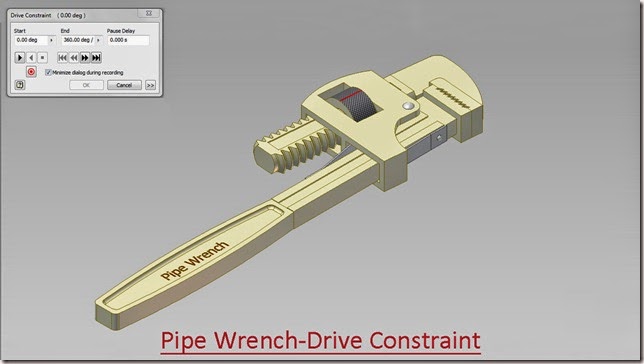
In this video, we will demonstrate how to apply the different type of mates in the assembly environment for creating the Dynamic Simulation of the ‘Pipe Wrench’.


download-Link


Click the following link to get the model file: - http://bit.ly/2mT1v8y


Transcription of Video

Display of Motion in ‘Pipe Wrench’ through Dynamic Simulation.

  1. Create a New ‘Standard (in).iam’ Assembly and save it with the name ‘Pipe Wrench-Dynamic Simulation’.
  2. Select Place component from the marking menu and place the ‘Base Frame’ in the Assembly.
  3. Re-orient the model in the design window by using View Cube.
  4. Set the current view as Home View by using the toggle next to View Cube.
  5. Place the ‘Supporting Bracket’ in the Assembly.
  6. Apply an Axis Mate between hole on the Base Frame and hole on the Supporting Bracket.
  7. Apply a Flush Mate Between XY Plane of Base Frame and XY Plane of Supporting Bracket.
  8. Activate Angle Constraint Command first select side face of Base Frame; then select side face of Supporting Bracket and at the last select top face of Supporting Bracket.
  9. Enter the value -4.76 degree in the Angle Input Box and click OK.
  10. Place the ‘Rivet-1’ in the Assembly.
  11. Fix the Rivet-1 in the hole of Supporting Bracket by the use of Insert Mate as displayed.
  12. Place the ‘Supporting Strip-1’ in the Assembly.
  13. Place the Supporting Strip -1 on the hole of Base Frame with the help of Insert Mate.
  14. Apply an Angle Constraint between top face of Supporting Strip -1 and top face of Base Frame.
  15. In the Solution Type, select Directed Angle.
  16. Place the ‘Rivet-2’ in the Assembly.
  17. Fix the Rivet-2 on the hole of Supporting Strip-1 with the help of Insert Mate.
  18. Place the ‘Supporting Strip-2’ in the Assembly.
  19. Place the Supporting Strip -2 on the hole of Base Frame with the help of Insert Mate.
  20. Apply an Angle Constraint between top face of Supporting Strip -2 and top face of Base Frame.
  21. In the Solution Type, select Directed Angle.
  22. Drag the Rivet-2 from the Browser Bar in the Assembly. This will place a copy of Rivet-2 in the Assembly.
  23. Fix the Rivet-2 on the hole of Supporting Strip-2 with the help of Insert Mate.
  24. Place the ‘Sliding Frame’ in the Assembly.
  25. Apply a Flush Mate between XY Plane of Base Frame and XY Plane of Sliding Frame.
  26. Set the browser from Assembly View to Modeling View using the toggle at the top of the browser.
  27. Apply a Mate Constraint between X Axis of Sliding Frame and Work Plane 7 of Supporting Bracket.
  28. Place the ‘Wheel’ in the Assembly.
  29. Apply a Mate Constraint between X Axis of Sliding Frame and Axis of Wheel.
  30. Apply a Mate Constraint between Work Plane 5 of Supporting Bracket and Work Plane 1 of Wheel.
  31. Apply a Mate Constraint between Jaw of Base Frame and Jaw of Sliding Frame in the Assembly.
  32. Select the previous applied ‘Mate: 5’ under the Constraints folder in the Browser Bar, Right click and choose ‘Supress’ from the context menu.
  33. Activate the Dynamic Simulation Tool from the Begin Panel of Environments Tab.
  34. Select Insert Joint in the Marking menu.
  35. Select ‘Screw’ from the drop down menu of Insert Joint dialog box.
  36. In the Insert Joint dialog box, select Circular edge of Sliding Frame in ‘Component 1’ selection option and select Circular edge of Wheel in ‘Component 2’ selection option.
  37. Enter the value 0.205 in the ‘Pitch’ input box. Click OK.
  38. Select Revolution:2 joint in the Browser under the Standard Joints folder, right click and select Properties from the context menu.
  39. Click dof 1 (R) tab and select Edit imposed motion button and check the Enable imposed motion option.
  40. Click the arrow to expand the input choices, and click Constant Value.
  41. Enter the value (-360/0.205) deg/s and click OK.
  42. In Simulation Player, fill the value 1000 in the Images field area.
  43. Clear the screen by activating the Clean Screen command.
  44. Click Run in the Simulation Player to display motion in Pipe Wrench.

Pipe Wrench-Drive Constraint-Autodesk Inventor 2012 (with caption and audio narration)


Pipe Wrench-Drive Constraint_1


Pipe Wrench-Drive Constraint_2  

Serial No. 75

Pipe Wrench-Drive Constraint-Autodesk Inventor 2012 (with caption and audio narration)

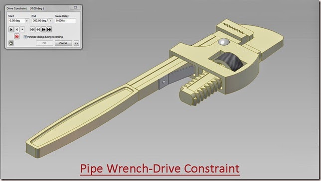
In this video, we will demonstrate how to apply the different type of mates in the assembly environment for creating the animation of the 'Pipe Wrench’.


  download-Link  


Click the following link to get the model file: - http://bit.ly/2njQE7E


Transcription of Video

Display of Motion in ‘Pipe Wrench’ through Drive Constraint.

  1. Create a New ‘Standard (in).iam’ Assembly and save it with the name ‘Pipe Wrench-Drive Constraint’.
  2. Select Place component from the marking menu and place the ‘Base Frame’ in the Assembly.
  3. Re-orient the model in the design window by using View Cube.
  4. Set the current view as Home View by using the toggle next to View Cube.
  5. Place the ‘Supporting Bracket’ in the Assembly.
  6. Apply an Axis Mate between hole on the Base Frame and hole on the Supporting Bracket.
  7. Apply a Flush Mate Between XY Plane of Base Frame and XY Plane of Supporting Bracket.
  8. Activate Angle Constraint Command first select side face of Base Frame; then select side face of Supporting Bracket and at the last select top face of Supporting Bracket.
  9. Enter the value -4.76 degree in the Angle Input Box and click OK.
  10. Place the ‘Rivet-1’ in the Assembly.
  11. Fix the Rivet-1 in the hole of Supporting Bracket by the use of Insert Mate as displayed.
  12. Place the ‘Supporting Strip-1’ in the Assembly.
  13. Place the Supporting Strip -1 on the hole of Base Frame with the help of Insert Mate.
  14. Apply an Angle Constraint between top face of Supporting Strip -1 and top face of Base Frame.
  15. In the Solution Type, select Directed Angle.
  16. Place the ‘Rivet-2’ in the Assembly.
  17. Fix the Rivet-2 on the hole of Supporting Strip-1 with the help of Insert Mate.
  18. Place the ‘Supporting Strip-2’ in the Assembly.
  19. Place the Supporting Strip -2 on the hole of Base Frame with the help of Insert Mate.
  20. Apply an Angle Constraint between top face of Supporting Strip -2 and top face of Base Frame.
  21. In the Solution Type, select Directed Angle.
  22. Drag the Rivet-2 from the Browser Bar in the Assembly. This will place a copy of Rivet-2 in the Assembly.
  23. Fix the Rivet-2 on the hole of Supporting Strip-2 with the help of Insert Mate.
  24. Place the ‘Sliding Frame’ in the Assembly.
  25. Apply a Flush Mate between XY Plane of Base Frame and XY Plane of Sliding Frame.
  26. Set the browser from Assembly View to Modeling View using the toggle at the top of the browser.
  27. Apply a Mate Constraint between X Axis of Sliding Frame and Work Plane 7 of Supporting Bracket.
  28. Place the ‘Wheel’ in the Assembly.
  29. Apply a Mate Constraint between X Axis of Sliding Frame and Axis of Wheel.
  30. Apply a Mate Constraint between Work Plane 5 of Supporting Bracket and Work Plane 1 of Wheel.
  31. Activate the Motion constraint, in the Type area select Rotation-Translation, and afterwards select the front face of Wheel then Vertical edge of Sliding Frame.
  32. Enter the value 0.205 inch in the Distance Input box and click OK.
  33. Activate the Angle Constraint, First select YZ Plane of Wheel, Second select XY Plane of Assembly and at last select top face of Supporting Bracket, and click OK.
  34. Apply a Mate Constraint between Jaw of Base Frame and Jaw of Sliding Frame in the Assembly.
  35. Select the previous applied ‘Mate: 5’ under the Constraints folder in the Browser Bar, Right click and choose ‘Supress’ from the context menu.
  36. Select the Angle:4 Constraint in the Browser and change its name as ‘Drive’ by clicking twice slowly.
  37. Right click the ‘Drive’ Constraint and select ‘Drive Constraint’ Tool from the context menu.
  38. In the Drive Constraint dialog box, set the End value to (360/0.205).
  39. Clear the screen by activating the Clean Screen command.
  40. Click the Forward Button to display motion in ‘Pipe Wrench’.
  41. To close the Jaw, click Reverse Button.

Hinge-Autodesk Inventor 2012 (with caption and audio narration)

Hinge_1 


Hinge_2

Serial No. 49

Hinge-Autodesk Inventor 2012 (with caption and audio narration)

download-Link 


Click the following link to get the model file: - http://bit.ly/2lHZ1cO


Transcription of Video

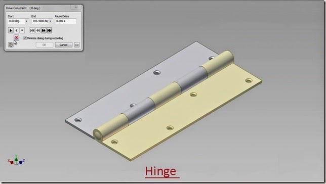
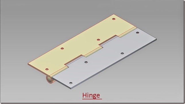
Hinge Modelling and apply motion in it through Drive-Constraint.

  1. Create a New ‘Standard (in).ipt’ Part file.
  2. Sketch1 is active by default.
  3. Draw a Rectangle 1.25 in. x 0.0625 in., coincident with Auto project part origin.
  4. Draw a Circle of 0.375 in. diameter.
  5. Apply a Tangent Constraint between circle and base line of the rectangle.
  6. Apply a Vertical Constraint between centre point of Circle and Auto project part origin.
  7. Draw another Circle of 0.25 in. diameter, Concentric with the previous one.
  8. Finish the Sketch.
  9. Start the Extrude command, select rectangle and the profile formed between the two circles.
  10. Enter the distance value 5 in. and select Symmetric option in the direction field.
  11. Click OK.
  12. Change the existing colour of the part into Popcorn.
  13. Save the file with the name Part 1.
  14. Create a new work plane 1 in. away from the front face of part.
  15. Start a new sketch on this Work Plane.
  16. Take the project of this edge of the part with Project Geometry Tool.
  17. Right click in the design window and select Slice Graphic from the context menu.
  18. By doing so hidden sketches behind the part will be seen clearly.
  19. Draw two lines to close the profile.
  20. Finish the Sketch.
  21. Start the Extrude command. It will automatic select the last drawn sketch profile, choose Cut option to remove the material from the part.
  22. Enter the distance value 1 in.
  23. Click ok.
  24. Start the Rectangular Pattern tool.
  25. Select Extrusion2 in the design window as feature.
  26. Click the ‘Direction 1’ button, and then select the outer edge of the Part1.
  27. Enter the value 2 in the column count input box.
  28. Enter the value 2 in. in the column spacing input box.
  29. Click OK.
  30. Take the project of edges of the model.
  31. Draw a rectangle coincident with the end point of the projected lines.
  32. Start the Offset tool, select the rectangle and drag the profile inside.
  33. A new Rectangle will be created.
  34. Place the dimension .25 in. as offset distance between the two rectangles.
  35. Start the Rectangular Pattern tool.
  36. Select bottom line of the rectangle.
  37. Click the ‘Direction 1’ button, and then select the vertical line of the rectangle. Click Flip button to change the direction of pattern.
  38. Enter the value 4 in the column count input box.
  39. Click the arrow button to expand the input choices in the column spacing input box.
  40. Choose ‘Measure’ option then select the vertical line of rectangle.
  41. Click more button to expand the dialogue box.
  42. Select ‘Fitted’ option and click OK.
  43. Convert all sketches into construction geometry.
  44. Hold the Ctrl Key and select the end points of these lines and convert them to centre point.
  45. Start the Hole Tool. The Points which we converted into centre point will be automatically selected.
  46. Set the diameter of the hole to 0.125 in.
  47. In the termination drop down menu select Through All option and Click OK.
  48. Start the Chamfer Tool.
  49. Select the top edges of all the holes.
  50. Enter the value 1/32 in. in the Distance field.
  51. Click OK.
  52. Save the file.
  53. Save As the same file with the name Part 2 also.
  54. This file will be used later in creation of Hinge Assembly.
  55. Close the file.
  56. Create a New Standard (in).iam Assembly file.
  57. Place the ‘Part 1’ file in the Assembly with aid of Place Component Tool.
  58. Save the Assembly with name ‘Hinge’.
  59. Place the ‘Part 2’ in the Assembly.
  60. Align ‘Part 2’ in correct position by using Rotate Component Tool.
  61. Some modifications are needed here in ‘Part 2’, so as to match it with Part 1.
  62. Select the Part 2 and double click it, to edit in the part modelling environment.
  63. Edit the Extrusion2 feature in the Browser Bar by double clicking it.
  64. In the Extrude2 dialogue box, change the direction of extrusion.
  65. In the same way, edit the Rectangular Pattern1.
  66. In the Column count input box, enter the value 3 and click OK.
  67. Click the Return icon, to return back in the Assembly modelling environment.
  68. Apply a mate constraint between the Axis of Part 1 and Part 2.
  69. Apply a Flush mate between the Front face of Part 1 and Part2.
  70. Right Click in the design window and select Create Component Tool from the marking menu.
  71. Give name of the part as ‘Centre Pin’.
  72. Click Ok.
  73. Select XY plane of Assembly, as a base plane for the new component.
  74. At present sketch1 is active of newly created Centre Pin.
  75. Take the project of edge of the hole.
  76. Finish the sketch.
  77. Start Extrude command. The sketch profile is automatically selected.
  78. In the extents drop down menu, select Between option.
  79. Select front face of part and then rear face of the part.
  80. Click ok.
  81. Change the model colour to Popcorn to distinguish it more clearly.
  82. Create a new sketch on the YZ plane of the Centre Pin.
  83. Take the project of front edge of the Centre Pin.
  84. Activate Slice Graphic Command from the Right click context menu.
  85. Draw a Three Point Rectangle, coincident with the midpoint and end point of the projected line.
  86. Apply a horizontal dimension of 0.03125 in. on the rectangle.
  87. Draw a Thee Point Arc inside the rectangle.
  88. Finish the sketch.
  89. Start Revolve command, first select the sketch profile and later the axis.
  90. Click OK.
  91. Start the Mirror Command from the Pattern Panel of the Model Tab.
  92. Select Revolve1 feature in the browser bar.
  93. Select Mirror Plane button in the Mirror dialogue box, then select XY plane of Centre Pin.
  94. Click Ok and return back to the assembly.
  95. Change the view of Assembly by using View Cube.
  96. Apply an Angle Constraint between Part1 and Part2, to show the motion in the Assembly of ‘Hinge’.
  97. Activate an Angle Constraint, first select the top face of Par1, then top face Part2, at last select the front face Part2.
  98. Click OK.
  99. Set the browser Assembly View to Modelling View using the toggle at the top of the Browser Bar.
  100. Select the Angle:1 constraint under Constraints folder in the Browser Bar and change its name as ‘Drive’ by clicking twice slowly.
  101. Right click the ‘Drive’ Constraint and select Drive Constraint from the context menu.
  102. In the Drive Constraint dialogue box, set End value to 191.42 deg.
  103. Click more button to expand the dialogue box and set the value for Increment 0.25 deg.
  104. In the Repetitions field select Start/End/Start and enter value 2.
  105. Clear the screen by activating the Clean Screen command, Click the Forward Button to display the motion in the ‘Hinge’ Assembly.

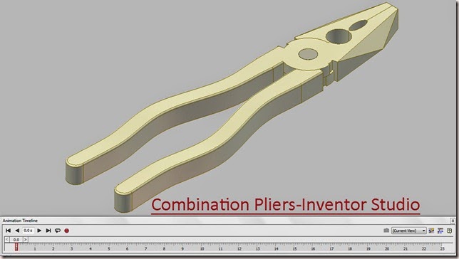
Combination Pliers-Inventor Studio-Autodesk Inventor 2012 (with caption and audio narration)

Combination Pliers-Inventor Studio_1 


Combination Pliers-Inventor Studio_2

Serial No. 22

Combination Pliers-Inventor Studio-Autodesk Inventor 2012 (with caption and audio narration)

In this video, we will demonstrate how to apply the different type of mates in the assembly environment for creating the animation of the ‘Combination Pliers’.


 download-Link 


Click the following link to get the model file: -http://bit.ly/2n4Yhig


Transcription of Video

Display of motion in ‘Combination Pliers’ through Inventor Studio

  1. Create a New ‘Standard (in).iam’ Assembly and save it with the name ‘Combination Pliers-Inventor Studio’.
  2. Select Place component from the marking menu and place the ‘Part1’ in the Assembly.
  3. Re-orient the model in the design window by using View Cube.
  4. Set the current view as Home View by using the toggle next to View Cube.
  5. Select the Part1 in the design window and remove its ‘Grounded’ position from the context menu.
  6. Apply an Axis Mate between Z Axis of Assembly and Z Axis of Part1.
  7. Apply a Mate Constraint between Centre Point of Assembly and Centre Point of Part1.
  8. Place the ‘Part2’ in the Assembly.
  9. Select the edge of small hole on Part2 to activate Assemble Tool.
  10. Then select the edge of small hole on Part1, click green check mark to place Insert Mate between Part2 and Part1.
  11. Activate an Angle Constraint, first Select face of Jaw of Part1, and then select YZ Plane of Assembly and in the end select top face of Part1. Click OK.
  12. Activate Angle Constraint once again, first Select face of Jaw of Part2, and then select YZ Plane of Assembly and in the end select top face of Part2.
  13. Enter the value 180 degree in the Angle Input box and Click Ok.
  14. Place the ‘Rivet’ in the Assembly.
  15. Select the inner circular edge of Rivet to activate Assemble Tool.
  16. Then select the inner small circular edge of hole on the Part2, click green check mark to place Insert Mate between Part2 and Rivet.
  17. Set the browser from Assembly View to Modeling View using the toggle at the top of the browser.
  18. Select ‘Angle:2’ under the Constraints folder in the Browser Bar, Right click and choose ‘Suppress’ from the context menu.
  19. Select Part1 and Part2 in the Browser Bar, right click and choose ‘Contact Set’ from the context menu.
  20. Select ‘Activate Contact Solver’ in the Interference panel of Inspect Tab.
  21. Drag the Part2, it will stop at the point of Collision between Part1 and Part2.
  22. Measure the swing angle between the jaw of Part1 and Part2. The detected swing angle is 40.18 degree.
  23. Restore the settings to previous state.
  24. Click the ‘Inventor Studio’ icon from the Begin Panel of Environments Tab.
  25. Select ‘Angle:1’ Constraint under Part1 in the Browser Bar, right click and select Animate Constraints in the context menu.
  26. In ‘Action’ section, enter the value -20.09 degree in the End input box.
  27. In the ‘Time’ section of Animate Constraint dialogue box, enter the value 10 second in the End input box.
  28. Click Acceleration Tab.
  29. Select ‘Constant Speed’ radio button in the Velocity Profile.
  30. Click OK.
  31. Select Expand Action Editor Button on the Animation Timeline.
  32. Select Angle:1 constraint in the Animation Timeline, right click and choose ‘Mirror’ from the context menu.
  33. Edit Mirrored animation action in the Animation Timeline.
  34. In the ‘Time’ section of Animate Constraint dialogue box, enter the value 13 second in the Start input box and enter the value 23 second in the End input box, to give effect of 3 second pause.
  35. Click OK.
  36. Select ‘Angle:2’ Constraint under Part2 in the Browser Bar, right click and select Animate Constraints in the context menu.
  37. In ‘Action’ section, enter the value (180+20.09) degree in the End input box.
  38. In the ‘Time’ section of Animate Constraint dialogue box, enter the value 10 second in the End input box.
  39. Click Acceleration Tab.
  40. Select ‘Constant Speed’ radio button in the Velocity Profile.
  41. Click OK.
  42. Select Angle:2 constraint in the Animation Timeline, right click and choose ‘Mirror’ from the context menu.
  43. Edit Mirrored animation action in the Animation Timeline.
  44. In the ‘Time’ section of Animate Constraint dialogue box, enter the value 13 second in the Start input box and enter the value 23 second in the End input box.
  45. Click OK.
  46. Select Collapse Action Editor Button on the Animation Timeline.
  47. Click the Animation Options Button.
  48. In the Animation Options dialogue box, click ‘Fit to Current Animation’ button in the ‘Length’ section option.
  49. Select Constant Speed radio button in the Default Velocity Profile and click Ok.
  50. Clear the screen by activating the Clean Screen command.
  51. Click ‘Go to Start’ Button.
  52. Click Play Animation button to display motion in Combination Pliers.

Sunday, December 8, 2013

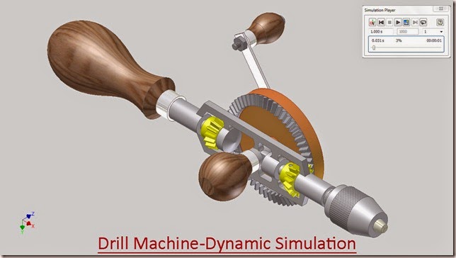
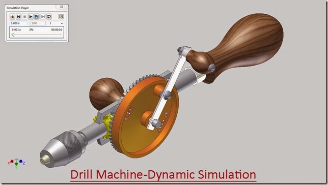
Drill Machine-Dynamic Simulation-Autodesk Inventor 2012 (with caption and audio narration)


Drill Machine-Dynamic Simulation_1


Drill Machine-Dynamic Simulation_2  


Serial No. 30

Drill Machine-Dynamic Simulation-Autodesk Inventor 2012 (with caption and audio narration)

In this video, we will demonstrate how to apply the different type of mates in the assembly environment for creating the Dynamic Simulation of the ‘Drill Machine’.


download-Link 


Click the following link to get the model file: -http://bit.ly/2ncLp9z


Transcription of Video

Display of Motion in Drill Machine through Dynamic Simulation

  1. Create a New ‘Standard (in).iam’ Assembly and save it with the name ‘Drill Machine-Dynamic Simulation’.
  2. Select Place component from the marking menu and place the Frame in the Assembly.
  3. Place Handle-1 and Handle Cap-1 in the Assembly.
  4. Start the Constrain Command and choose Insert Mate from the type option.
  5. First select the inner circular edge of Handle Cap, then select outer circular edge of Handle and click Ok.
  6. Give another Insert Mate between Inner edge of Handle Cap and circular edge of Frame as displayed.
  7. Re-orient the design window using View Cube.
  8. Set the current view as Home View using the toggle next to View Cube.
  9. Place Gear Wheel and Gear in the Assembly.
  10. Apply a Mate Constraint between Axis of Gear Wheel and Axis of Gear.
  11. Next, apply a Mate Constraint between face of Gear Wheel and face of Gear.
  12. Apply another Mate Constraint between YZ Plane of Gear Wheel and XZ Plane of Gear.
  13. Re-orient the Gear Wheel with respect to Frame using Rotate Component Tool.
  14. Apply an Axis Mate between Gear Wheel and stud of Frame.
  15. Place Spindle in the Assembly.
  16. Apply a Mate Constraint between Axis of Frame and Axis of Spindle.
  17. Next, apply a Mate Constraint between inner face of supporting cylinder of frame and back face of the spindle.
  18. Place Pinion-2 in the Assembly.
  19. Apply a Mate Constraint between Axis of Pinion-2 and Axis of Spindle.
  20. Apply an Axis Mate between hole on Pinion-2 and hole on Spindle.
  21. Place Locking Pin in the Assembly and fix it inside the hole of Pinion using Insert Mate.
  22. Place Pinion-1 in the Assembly.
  23. Align the Pinion-1 to match it with the Frame.
  24. Apply a Mate Constraint between Axis of Frame and Axis of Pinion-1.
  25. Select Pinion-1, Pinion-2 and Gear, then right click in the design window, choose ‘Isolate’ from the context menu.
  26. Set the Browser from Assembly view to Modeling View.
  27. Locate the Intersection Point of Pinion-2 inside the Browser Bar.
  28. Apply a Mate Constraint between the Intersection Point of Pinion-2 and Intersection Point of Gear.
  29. In the same manner, apply a Mate Constraint between the Intersection Point of Pinion-2 and the Intersection Point of Pinion-1.
  30. Activate Motion Constraint; first select the Axis of Pinion-1 and afterward the Axis of Gear.
  31. Enter the value 15/56 in the Ratio Input box and click Apply.
  32. Apply same step as above to give motion constraint between Pinion-2 and Gear.
  33. Right click in the design window, choose Undo Isolate from the context menu.
  34. Place Chuck in the Assembly.
  35. Apply a Mate Constraint between the Axis of Spindle and the Axis of Chuck.
  36. Place a Mate Constraint between inner circular face of Chuck and front face of Spindle.
  37. Place another Mate Constraint between YZ Plane of Chuck and YZ Plane of Spindle.
  38. Place Three instances of Jaw in the Assembly.
  39. Apply an Axis Mate between two subsequent Jaws.
  40. Next, apply a Mate between their edges.
  41. Apply a Flush Mate between their end faces.
  42. In the same manner, constraint the third Jaw.
  43. Apply a Mate Constraint between inner circular face of Chuck and rear face of Jaw.
  44. Apply a Mate Constraint between the Axis of Chuck and the Axis of Jaw.
  45. Place a Mate Constraint between YZ Plane of Chuck and YZ Plane of any one Jaw.
  46. Place Handle-2 and Handle Cap-2 in the Assembly.
  47. Apply an Insert Mate between inner circular edge of Handle Cap-2 and outer circular edge of Handle-2.
  48. Position the Handle Cap-2 in respect of the stud of Frame by using Rotate Component Tool.
  49. Apply an Insert Mate between front circular edge of Handle Cap-2 and inner circular edge of stud.
  50. Place Handle Connecting Plate in the Assembly.
  51. Apply an Insert Mate between edge of the hole on Handle Connecting Plate and inner circular edge of stud.
  52. Place Washer-1 in the Assembly.
  53. Apply an Insert Mate between edge of the hole on Washer-1 and edge of the hole on Gear Wheel.
  54. Apply a Mate Constraint between YZ Plane of Handle Connecting Plate and Axis of the hole on Gear Wheel.
  55. Place Screw-2 in the Assembly.
  56. Apply an Insert Mate between inner circular edge of Screw-2 and edge of the hole on Handle Connecting Plate.
  57. Place Handle-3 and Handle Cap-3 in the Assembly.
  58. Fit the Handle Cap-3 over the Handle-3 with the help of Insert Mate.
  59. Apply another Insert Mate between the Handle Cap-3 and hole on the Handle Connecting Plate.
  60. Place Screw-1 and Nut in the Assembly.
  61. Fix the Screw-1 on the Handle-3 with the help of Insert Mate.
  62. Fix the Nut on the Screw-1 by applying Insert Mate.
  63. Open the Visibility of surfaces named ‘Pitch Diameter’ of Pinion-2, Pinion-1 and Gear.
  64. ‘Isolate’ the Pinion-1, Pinion-2 and Gear in the Assembly.
  65. Activate the Dynamic Simulation Tool from the Begin Panel of Environments Tab.
  66. Select Insert Joint in the Marking menu.
  67. Select ‘Rolling: Cone on Cone’ from the drop down menu of Insert Joint dialog box.
  68. Select Pitch Diameter of Pinion-2 in ‘Component 1’ option and select Pitch diameter of Gear in ‘Component 2’ option and click Apply.
  69. In the same manner select Pitch Diameter of Pinion-1 and select Pitch diameter of Gear and click Ok.
  70. Finish Dynamic Simulation and return to Assembly Modelling environment.
  71. Close the visibility of surfaces named ‘Pitch Diameter’ of Pinion-1, Pinion-2 and Gear.
  72. Right Click in the design window and click ‘Undo Isolate’ option.
  73. Activate Dynamic Simulation Tool.
  74. Select Revolution:2 joint in the Browser under the Standard Joints folder, right click and select Properties from the context menu.
  75. Click dof 1 (R) tab and select Edit imposed motion button and check the Enable imposed motion option.
  76. Click the arrow to expand the input choices, and click Constant Value.
  77. Enter the value 360 deg/s and click Ok.
  78. In Simulation Player, fill the value 1000 in the Images field area.
  79. Clear the screen by activating the Clean Screen command.
  80. Click Run in the Simulation Player to display motion in Drill Machine.

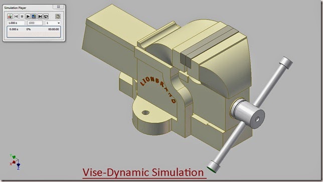
Vise-Dynamic Simulation-Autodesk Inventor 2012 (with caption and audio narration)

Vise-Dynamic Simulation_1 


Vise-Dynamic Simulation_2

Serial No. 106

Vise-Dynamic Simulation-Autodesk Inventor 2012 (with caption and audio narration)

In this video, we will demonstrate how to apply the different type of mates in the assembly environment for creating the Dynamic Simulation of the ‘Vise’.

download-Link 


Click the following link to get the model file: - http://bit.ly/2ms77GX


 Transcription of Video

Display of Motion in Vise through Dynamic Simulation

Sub Assembly-1:

  1. Create a New ‘Standard (in).iam’ Assembly and save it with the name ‘Sub Assembly-1’.
  2. Select Place component from the marking menu and place the ‘Base Housing’ in the Assembly.
  3. Re-orient the model in the design window by using View Cube.
  4. Set the current view as Home View by using the toggle next to View Cube.
  5. Place the ‘Part-1’ in the Assembly.
  6. Apply a Mate Constraint between the bottom face of Part-1 and inner face of Base Housing.
  7. Apply another Mate Constraint between YZ plane of Base Housing and YZ Plane of Part-1.
  8. Apply a Flush Mate between front face of Part-1 and front face of Base Housing.
  9. Fill the offset value 5.672 inch.
  10. Place the ‘Jaw Plate’ in the assembly.
  11. Apply a Mate Constraint between slotted face of Base Housing and back face of Jaw Plate.
  12. Next apply a Mate Constraint between lower face of slotted face and bottom Face of Jaw Plate.
  13. Apply a Flush Mate between the side face of Jaw Plate and side face of Base Housing.
  14. Place two identical ‘Screws’ in the Assembly.
  15. Fix both the Screws in the holes on Jaw Plate by using the Insert Mate.
  16. Save the Sub Assembly-1 and close it.

Sub Assembly-2:

  1. Create a New Assembly and save it with the name ‘Sub Assembly-2’.
  2. Select Place component from the marking menu and place the ‘Sliding Housing’ in the Assembly.
  3. Re-orient the model in the design window by using View Cube.
  4. Set the current view as Home View by using the toggle next to View Cube.
  5. Place the ‘Jaw Plate’ in the Assembly.
  6. Apply a Mate Constraint between slotted face of Sliding Housing and back face of Jaw Plate.
  7. Next apply a Mate Constraint between lower face of slotted face and bottom Face of Jaw Plate.
  8. Apply a Flush Mate between the side face of Jaw Plate and side face of Sliding Housing.
  9. Place two identical ‘Screws’ in the Assembly.
  10. Fix both the Screws in the holes on Jaw Plate by using the Insert Mate.
  11. Save the Sub Assembly-2 and close it.

Sub Assembly-3:

  1. Create a New Assembly and save it with the name ‘Sub Assembly-3’.
  2. Select Place component from the marking menu and place the ‘Threaded Spindle’ in the Assembly.
  3. Place the ‘Compress Spring’ in the Assembly.
  4. Apply a Mate Constraint between Y Axis of Compress Spring and Axis of Threaded Spindle.
  5. Apply a Mate Constraint between circular face of Threaded Spindle and face of Compress Spring.
  6. Place the ‘Washer’ in the Assembly.
  7. Apply an Axis Mate between Washer and Threaded Spindle.
  8. Apply a Mate Constraint between face of Washer and face of Compress Spring.
  9. Place the ‘Pin’ in the Assembly.
  10. Apply an Axis Mate between Pin and hole on the Threaded Spindle.
  11. Apply a Mate Constraint between XY Plane of Threaded Spindle and YZ Plane of Pin.
  12. Place the ‘Handle’ in the Assembly.
  13. Apply an Axis Mate between hole on the Threaded Spindle and Handle.
  14. Next apply a Mate Constraint between XZ plane of Threaded Spindle and YZ Plane of Handle.
  15. Save the Sub Assembly-3 and close it.

Main Assembly (Vise):

  1. Create a New Assembly and save it with the name ‘Vise-Dynamic Simulation’.
  2. Select Place component from the marking menu and place the ‘Sub Assembly-1’ in the Assembly.
  3. Re-orient the model in the design window by using View Cube.
  4. Set the current view as Home View by using the toggle next to View Cube.
  5. Place ‘Sub Assembly-2’ in the Assembly.
  6. Align the Sub Assembly-2 in front of Sub Assembly-1 by using Rotate Component Tool.
  7. Apply a Mate Constraint between the bed of Sub Assembly-1 and bottom face of Sub Assembly-2.
  8. Apply a Flush Mate between YZ Plane of Sub Assembly-1 and XY Plane of Sub Assembly-2.
  9. Place ‘Sub Assembly-3’ in the Assembly.
  10. Apply an Axis Mate between hole on the Sliding Housing and Threaded Spindle.
  11. Apply a Mate Constraint between outer rim of hole on Sliding Housing and rear face of Threaded Spindle.
  12. Apply a Mate Constraint between subsequent faces of Jaw in the Assembly.
  13. Select the previous applied ‘Mate:4’under the Sub Assembly-1 in the Browser Bar, Right click and choose ‘Supress’ from the context menu.
  14. Dynamic Simulation
  15. Activate the Dynamic Simulation Tool from the Begin Panel of Environments Tab.
  16. Select Insert Joint in the Marking menu.
  17. Select ‘Screw’ from the drop down menu of Insert Joint dialog box.
  18. In the Insert Joint dialog box, select Circular edge of Threaded Spindle in ‘Component 1’ selection option and select Circular edge of Part-1 in ‘Component 2’ selection option.
  19. Enter the value 1/7 in the ‘Pitch’ input box. Click OK.
  20. Select Revolution:2 joint in the Browser under the Standard Joints folder, right click and select Properties from the context menu.
  21. Click dof 1 (R) tab and select Edit imposed motion button and check the Enable imposed motion option.
  22. Click the arrow to expand the input choices, and click Constant Value.
  23. Enter the value -360*7 deg/s and click OK.
  24. In Simulation Player, fill the value 1000 in the Images field area.
  25. Clear the screen by activating the Clean Screen command.
  26. Click Run in the Simulation Player to display motion in Vise.
  27. Change the colour of Vise ‘Green (Clear)’ to watch its motion in transparent view.