Wednesday, January 29, 2014

Modeling a Link of a Chain (Pro E Wildfire)

Link Chain

The following video will display the modelling of Link of a Chain.

This is a part modelling video, so viewers will see the application of many part modelling tools of Pro E Wildfire 5.0 (Extrude, Hole, Mirror, Round etc.) as well as 2D sketch tools.


download-Link


To get finished files displayed in the video visit following link----- http://bit.ly/2nrq6kU


I have used this 'Link' in the creation of Chain Animation in the past, whose video 'Chain-Inventor Studio Autodesk Inventor is available on the following link: ---

http://nisheeth-inventortalks.blogspot.com/2011/05/chain-inventor-studio-video-tutorial.html

Tuesday, January 28, 2014

Application of ‘Contour Flange’ & ‘Contour Roll’ tool-Autodesk Inventor 2013 (with caption and audio)

Application of 'Contour Flange' and 'Contour Roll' tool

Serial No. 199

Application of ‘Contour Flange’ & ‘Contour Roll’ tool-Autodesk Inventor 2013 (with caption and audio)


Transcription of Video

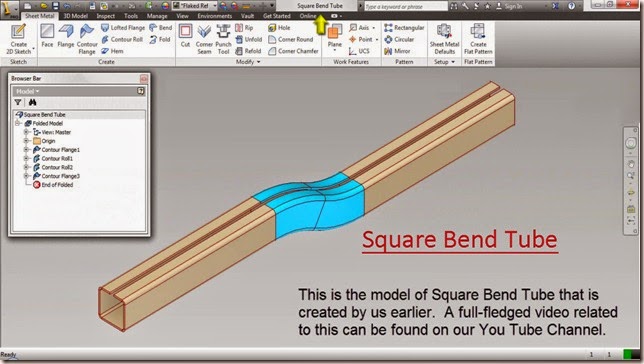
  1. This is the model of Square Bend Tube that is created by us earlier. A full-fledged video related to this can be found on our You Tube Channel.

  2. Here from the Browser Bar you can check the history of its modelling. Contour Flange and Contour Roll were used to create this model.

  3. In this video we will describe about the aforesaid features and show how they work.

      Contour Flange Feature

      1. Contour Flange tool is available on Create panel of Sheet Metal Tab.

      2. Contour Flange is used when you have created an open sketch profile with the help of lines, arcs, splines or elliptical arcs etc. and you want to create a flange on basis of it.

      3. When you want to create a flange on basis of a sketch profile created with the help of lines, arcs, splines or elliptical arcs etc. then Contour Flange is used.

      4. The most important requirement for this tool is an open sketch profile; you cannot use this tool with a closed sketch profile.

          Contour Flange applied in the modelling of Square Bend Tube (First instance)

          1. This is the open sketch profile that is used for flange creation.

          2. After activating the Contour Flange Tool, select the sketch profile that is visible in the graphics window.

          3. Distance is automatically set as Width Extents Type.

          4. Distance value 200 mm is filled already.

          5. From here you can flip the extent direction.

          6. Click OK to create the Contour Flange feature.

              Contour Flange applied in the modelling of Square Bend Tube (Second instance)

              1. This time the visible projected edge of the model will be used to create sheet metal flange.

              2. Activate the tool and select the visible sketch having the projected edges of the model.

              3. Expand the more button to find additional option of Contour Flange dialogue box.

              4. Set the Width Extents Type to Distance.

              5. Fill the distance value 200 mm.

              6. Click OK to create the Contour Flange feature.

                  Contour Roll Feature

                  1. Contour Roll Feature is used to revolve an open sketch profile around an axis to develop a sheet metal flange.

                  2. This tool is available on the Create panel of Sheet Metal Tab.

                      Contour Roll applied in the modelling of Square Bend Tube (First instance)

                      1. This is the open sketch profile consisting projected model edges and an axis.

                      2. After activating the Contour Roll Tool, select the sketch profile visible in the graphics window.

                      3. Now Axis selection is active so select the axis for revolution.

                      4. Fill 30 degree in Rolled Angle input box.

                      5. Click OK to close the Contour Roll dialogue box.

                          Contour Roll applied in the modelling of Square Bend Tube (Second instance)

                          1. This time the visible projected edge of the model will be used to create sheet metal flange.

                          2. Activate the Contour Roll Tool and follow the same procedure, as applied earlier to create the Contour Roll feature.

                          3. The final result is visible in the design window.

                          Monday, January 27, 2014

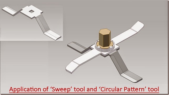
                          Application of ‘Sweep' tool and ‘Circular Pattern’ tool-Autodesk Inventor 2013 (with caption and audio)

                          Application of ‘Sweep’ tool and ‘Circular Pattern’ tool

                          Serial No. 198

                          Application of ‘Sweep' tool and ‘Circular Pattern’ tool-Autodesk Inventor 2013 (with caption and audio)

                          In this exercise we will create a new part named ‘Blade-base’, related to our previously created full-fledged model ‘Mixer (Cabinet)’.

                          In this part file we will utilize following feature/tools: - 2D Sketches, work planes, extrude, fillet, sweep and circular pattern.


                          download-Link 


                          Click the following link to get the model file: - http://bit.ly/2nMCMms


                          Transcription of Video

                          1. Create a New Standard (in).ipt file.
                          2. Create a new sketch on the XY Plane with the aid of ‘Create 2D Sketch’ tool.
                          3. Draw the sketch diagram of part ‘Blade-base’ with the help of line tool.
                          4. Pick up the Offset tool and select all lines in the graphics window.
                          5. Enter the offset distance 1/16 inch between these two lines.
                          6. Close the sketch profile by adding lines where the gap exists.
                          7. Now the sketch is complete.
                          8. Finish the 2D sketch.
                          9. Select any one of the line of enclosed profile, the mini-toolbar will appear in the graphics window.
                          10. Click the ‘Create Extrude’ icon.
                          11. It will automatically select the enclosed profile.
                          12. Extrude dialogue box is visible in the graphics window.
                          13. In the Extents field, select ‘Symmetric’ option.
                          14. Enter the distance value 3/8 inch.
                          15. Click OK to create the extrude feature.
                          16. Change the model colour to ‘Steel’.
                          17. Save the file with the name ‘Blade-base’.
                          18. Activate the Fillet tool from the Modify panel of 3D Model tab.
                          19. Fillet dialogue box is visible in the graphics window.
                          20. Select four bend edges of the model.
                          21. Set the value to 1/16 inch in ‘Radius’ field.
                          22. Click OK to create the fillet feature.
                          23. Now make some changes in the settings of the software.
                          24. Go to the Options panel of Tools tab and click Application Options icon.
                          25. Application Options dialogue box is visible in the graphics window.
                          26. General tab is active by default.
                          27. Switch to Sketch tab.
                          28. Click on the Standard Toggle box of 'Autoproject edges for sketch creation and edit' option.
                          29. Apply and close the dialogue box.
                          30. Create a new sketch on the blue face of the model, it will be used as a profile for the sweep.
                          31. Select the projected model edges in the graphics window and convert them into construction geometry.
                          32. Draw a line from Point1 of length 1/8 inch, parallel to Z direction of prevailing 3D indicator in the graphics window.
                          33. Draw another line from the same Point1 of length 3/64 inch, parallel to Y direction.
                          34. Close the profile by adding a new line.
                          35. Finish the 2D Sketch.
                          36. On the Ribbon click ‘Plane’ icon on the Work Features panel of 3D Model tab.
                          37. Click on Point2 and select corresponding edge of the model (indicated by red colour).
                          38. Work Plane has been created, perpendicular to this edge.
                          39. Create a new sketch on this Work Plane to create a path for sweep.
                          40. Right click in the graphics window and choose ‘Slice Graphics’ option.
                          41. Take the project of the model by using ‘Project Cut Edges’ tool.
                          42. Convert the entire projected model edges into construction geometry except yellow coloured line and arc.
                          43. Add a new line starting from Point3 of length 0.75833 inch over the projected model edge indicated by yellow colour.
                          44. Finish the 2D Sketch.
                          45. Activate the ‘Sweep’ tool from Create panel of 3D Model tab.
                          46. Sweep dialogue box is visible in the graphics window.
                          47. Since there is only one closed profile, the profile drawn on Sketch2 is selected automatically.
                          48. The Path selection button is active in the Sweep dialogue box.
                          49. Select the sketch profile drawn on Sketch3 as sweep path in the graphics window.
                          50. Select ‘Cut’ option to remove the material.
                          51. Click OK to execute the Sweep feature.
                          52. On the Ribbon click ‘Circular Pattern’ icon on the Pattern panel of 3D Model tab.
                          53. Circular Pattern dialogue box is visible in the graphics window.
                          54. In the Circular Pattern dialogue box, ‘Features’ selection button is activated by default.
                          55. Select the ‘Sweep1’ in the Browser Bar as feature to pattern.
                          56. Right click in the graphics window and choose Continue from the context menu.
                          57. Select the Y Axis in the Browser Bar to define axis of revolution.
                          58. Set the pattern count value 2 in the ‘Placement’ field.
                          59. Leave the pattern angle 360 degree unchanged which is set by default.
                          60. Click OK to execute the Circular Pattern feature.
                          61. Create a new sketch on the blue face of ‘Blade-base’.
                          62. Draw a square of length ¾ inch with the aid of ‘Three Point Centre Rectangle’ tool, coincident with autoprojected part origin.
                          63. Activate the ‘Three Point Centre Rectangle’ from the Draw panel of Sketch tab.
                          64. Click on Point4 to set the center point of the rectangle.
                          65. Right click in the graphics window and click OK to finish the rectangle command.
                          66. Exit the sketching environment.
                          67. Activate the Extrude command from the marking menu.
                          68. And select the square.
                          69. In the Extents field, select ‘To’ option from the drop down list.
                          70. Select back face of the model and choose Join option.
                          71. Click OK to create Extrude feature.
                          72. Create a new sketch once again on the blue face of model.
                          73. Draw another square of length 3/16 inch.
                          74. Use this square to remove material from the model by using Extrude tool.

                          Thursday, January 23, 2014

                          Application of ‘Circular Pattern’ tool-Autodesk Inventor 2013 (with caption and audio narration)

                          Application of ‘Circular Pattern’ tool

                          Serial No. 197

                          Application of ‘Circular Pattern’ tool-Autodesk Inventor 2013 (with caption and audio narration)


                          Transcription of Video

                          1. This is the model of Twist Drill that is created by us earlier. A full-fledged video related to this can be found on our You Tube Channel.
                          2. Here from the Browser Bar you can check the history of its modelling. A lot of 2D sketches, Extrude, Coil features, Work features and Circular Pattern were utilized to create this model.
                          3. In this video we will describe about the Circular Pattern Tool that was used three times in its modelling. Watch the video to understand how the tool works.
                          4. Circular Pattern tool duplicates one or more features and arrange the resulting occurrences by a specific count and spacing in a circular path.
                          5. This tool is available on Pattern Panel of Model Tab.
                          6. First Circular Pattern Applied in the modeling of Twist Drill
                          7. After activating the Circular Pattern tool the Coil1 and Extrude2 are being selected as feature for the duplication.
                          8. Z axis of the model has been selected as axis of revolution.
                          9. The number of occurrences in the pattern is 2.
                          10. Degree of rotation is 180.
                          11. After clicking the ok button the result is in front of you. A duplicate feature is created easily.
                          12. Watch the past and current position of the model by suppressing and un-supressing the feature.
                          13. Second Circular Pattern Applied in the modeling of Twist Drill.
                          14. This time Extrude4 is selected as feature and the Rotation of Axis is same that is the Z axis of the model.
                          15. The Occurrence count will be 2 and the Occurrence angle180 degree.
                          16. After clicking the ok button the duplicate feature is created.
                          17. Third Circular Pattern Applied in the modeling of Twist Drill.
                          18. This time two Coil features are selected for the duplication.
                          19. All the other specifications of the Circular pattern will be the same as previous ones.
                          20. The final result is visible in the design window.

                          Application of ‘Sweep’ tool and ‘Shell’ tool-Autodesk Inventor 2013 (with caption and audio narration)

                          Application of ‘Sweep’ tool and ‘Shell’ tool

                          Serial No. 196

                          Application of ‘Sweep’ tool and ‘Shell’ tool-Autodesk Inventor 2013 (with caption and audio narration)

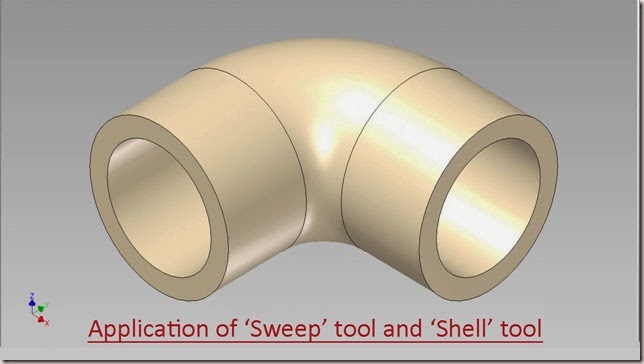
                          In this exercise we will create a new part, related to our previously created full-fledged model ‘Elbow’.

                          In this part file we will create some 2D Sketches, work planes, sweep & shell features.

                           download-Link


                          Click the following link to get the model file: - http://bit.ly/2nPe9Wf


                          Transcription of Video

                          1. Create a New Standard (in).ipt file.
                          2. Create a 2D Sketch on the XY Plane.
                          3. Draw a line of length 1.1875 inch, coincident with the auto projected part origin and parallel to X axis.
                          4. Right click in the graphics window and select ‘Create Line’ tool.
                          5. Click the green point in the graphics window as start point of the line.
                          6. And enter the value 1.1875 inch.
                          7. Right click in the graphics window and click OK to finish the command.
                          8. Create another line of length 1.1875 inch, parallel to Y axis and coincident with the origin.
                          9. Select these two lines and change the colour to White.
                          10. On the Ribbon click ‘Fillet’ icon on the Draw panel of Sketch tab.
                          11. 2D Fillet dialogue box is visible in the graphics window.
                          12. Enter the value 0.625 inch in the 2D fillet dialogue box.
                          13. And select these two lines in the graphics window to apply the fillet.
                          14. Right click in the graphics window and click OK to exit the command.
                          15. Finish the 2D Sketch.
                          16. On the Ribbon click ‘Plane’ icon on the Work Features panel of 3D Model tab.
                          17. Click one of the end points of the line and select this line in the graphics window.
                          18. Work Plane has been created, perpendicular to this line.
                          19. Create a new sketch on this Work Plane.
                          20. Draw a Circle of diameter 1 inch on the end point of the line.
                          21. Finish the 2D Sketch.
                          22. Activate the ‘Sweep’ tool from Create panel of 3D Model tab.
                          23. Sweep dialog box is visible in the graphics window.
                          24. Since there is only single closed profile, the profile drawn on sketch 2 is selected automatically.
                          25. The path selection button is active in the Sweep dialogue box.
                          26. Select the ‘Sketch1’ in the graphics window as sweep path.
                          27. Click OK to execute the Sweep feature.
                          28. Change the model colour to ‘Flaked Reflective – Beige’.
                          29. Save the Part file with the name ‘Elbow’.
                          30. On the Ribbon click ‘Shell’ tool icon on the Modify panel of 3D Model tab.
                          31. Shell dialog box is visible in the graphics window.
                          32. ‘Remove Faces’ selection button is activated by default.
                          33. Select both blue faces of the Elbow.
                          34. Enter the value 0.125 inch in the ‘Thickness’ field.
                          35. Click OK to apply the Shell feature.

                          Monday, January 20, 2014

                          Application of ‘Loft’ tool Ex.1-Autodesk Inventor 2013 (with caption and audio narration)

                          Application of 'Loft' tool Ex.1

                          Serial No. 195

                          Application of ‘Loft’ tool Ex.1-Autodesk Inventor 2013 (with caption and audio narration)

                          In this exercise, we are using a partially constructed assembly of ‘Grating for Gas Oven’. We will add some 2D sketches, work planes and a loft feature to proceed towards its completion.

                          download-Link 

                          Click the following link to get the model file: - http://bit.ly/2otrMLl 


                          Transcription of Video

                          1. Open the ‘Grating for Gas Oven’ (.iam) file.
                          2. Here a pre constructed ‘Part1’ is visible in this Assembly.
                          3. Activate the ‘Create Component’ tool to create a new part in the Assembly.
                          4. Select the XY Plane of the assembly as a base plane for the new component.
                          5. Create a new sketch on the XY Plane of the ‘Part2’.
                          6. Take the project of Part1 by using ‘Project Cut Edges’ tool.
                          7. Select the projected model edges in the graphics window and convert them into construction geometry.
                          8. On the Ribbon, click 'Finish Sketch' icon.
                          9. Now we will create a new work plane, parallel to YZ Plane of Part2 with the aid of ‘Offset from Plane’ tool.
                          10. Activate the ‘Offset from Plane’ tool from the Work Features panel of 3D Model tab.
                          11. Select YZ Plane of ‘Part 2’ from the Browser Bar.
                          12. Mini toolbar appears in the graphics window.
                          13. Drag the manipulator arrow button in the graphics window.
                          14. Enter the offset distance value (-1.875) inch.
                          15. Click OK to create a new work plane.
                          16. Create a new sketch on this work plane.
                          17. Take the project of bottom edge of the Part1 and Y Axis of Part2.
                          18. Convert both the projected edges into construction geometry.
                          19. Draw a rectangle of value 0.25 inch X 0.349 inch with the help of ‘Three Point Center Rectangle’ tool.
                          20. Apply a dimension of 0.2991 inch between center point of rectangle and projected edge of Part1.
                          21. Finish the 2D Sketch.
                          22. Create a new work plane parallel to Work Plane1 at an offset distance of 3.25 inch.
                          23. Close the visibility of Work Plane1.
                          24. Create a new sketch on Work Plane2.
                          25. Take the project of top line of previously drawn rectangle.
                          26. Close the visibility of Sketch1 and Sketch2 from the Browser Bar to clear the screen.
                          27. Take the project of Y Axis of Part2.
                          28. Create a new line of 0.4040 inch with the aid of Offset tool.
                          29. Apply a Coincident Constraint between midpoint of newly created line and projected Y Axis line.
                          30. Apply 0.59860 inch dimension between these lines.
                          31. Add two more lines to close the profile.
                          32. Finish the 2D Sketch.
                          33. Open the visibility of Sketch2 from the Browser Bar.
                          34. Activate the ‘Loft’ tool from Create panel of 3D Model tab.
                          35. Loft dialogue box is visible in the graphics window.
                          36. On the ‘Curves’ tab, specify the sections to loft.
                          37. Click under the ‘Sections’ heading and the select both the sketch profiles in the graphics window.
                          38. Click OK to execute the Loft feature.
                          39. Close the visibility of Sketch2 and Work Plane2 from the Browser Bar.
                          40. Change the colour of model to Steel.
                          41. Return back to the Assembly environment.

                          Sunday, January 19, 2014

                          Creating Lines in a 2D sketch in Autodesk Inventor 2013

                          Creating Lines in a 2D sketch (Autodesk Inventor 2013)

                          Video Tutorial with caption and audio narration


                          Transcription of Video

                          1. Open a new standard (mm).ipt file from the scratch.
                          2. To start a new sketch, click Create 2D Sketch icon present on the sketch panel of 3D Model Tab.
                          3. Select any of the work plane to start the sketching.
                          4. Select Front in view cube to adjust the design window.
                          5. If your design window looks different change the settings of your software in following way.
                          6. Click the Tools Tab and activate the Application Option Tool.
                          7. General Tab is displayed by default.
                          8. Now click the Sketch Tab.
                          9. Make sure the settings of your software should be same as displayed here.
                          10. Applying the setting and close the dialogue box.
                          11. Now activate the sketch Tab to display the sketching tools.
                          12. Line tool is located in Draw Panel of Sketch Tab.
                          13. Click on its Icon to activate the tool.
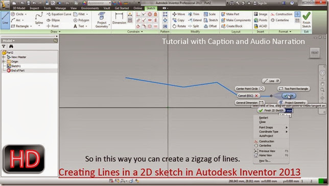
                          14. Click anywhere in design window to place a start point of the line and then click again to place the end point of the line.
                          15. So in this way you can create a zigzag of lines.
                          16. To draw a defined length of line you can take the help of heads up display.
                          17. If heads up display is not enabled in your software you can turn it on from the Application option.
                          18. You can control the settings of heads up display by clicking its setting tab.
                          19. By the heads up display you can define a point’s X and Y location.
                          20. You can also define the length and angle of a line.
                          21. A dimension will be automatically applied when a dimension is filled.
                          22. You can activate line tool even by marking menu.
                          23. Click Tab key on your keyboard and fill 0 in the X input box. Click tab key again to switch to Y tab and fill the value 50.
                          24. Click Enter key to place the start of line.
                          25. Use tab key of your keyboard to switch between heads up input box and use enter key to place the points in the design window.
                          26. With the help of Line Tool, you can even create Tangent Arcs.

                          Creating a new Part on the curve surface in Assembly-Autodesk Inventor 2013 (with caption and audio)

                          Creating a Part over the curve surface of another part

                          Serial No. 194

                          Creating a new Part on the curve surface in Assembly-Autodesk Inventor 2013 (with caption and audio)

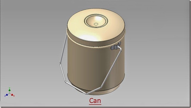
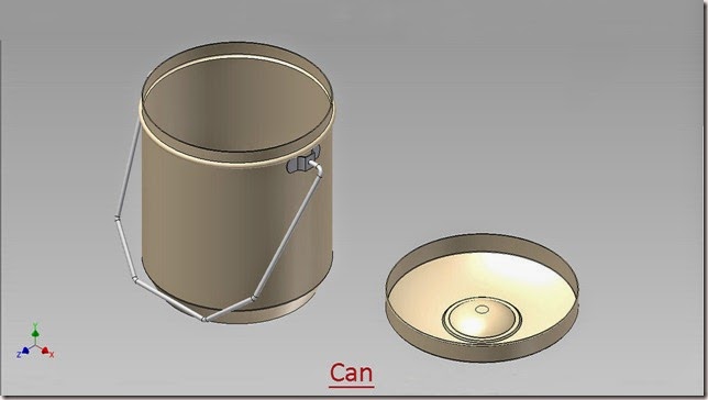
                          In this exercise, a pre constructed part file (Base) is utilized, which is taken from our model ‘Can’.

                           download-Link


                          Click the following link to get the model file: - http://bit.ly/2nO8BeB


                          Transcription of Video

                          We have following cylindrical component named ‘Base’ in our incomplete assembly.

                          The target is to create and fix a ‘Clip’ on its cylindrical face.

                          1. Now create a new component in the assembly with the name ‘Clip’.
                          2. Select the Standard (in).ipt template for the new part file.
                          3. Select the Centre point of the assembly as a base plane for the new component.
                          4. Return back to the assembly environment by clicking Return icon.
                          5. At present the part is not fully constrained in the assembly.
                          6. Remove the degrees of freedom of the component (Clip) by applying Mate constraints.
                          7. So, after applying the Mate constraints no degrees of freedom is left in the Assembly.
                          8. Double click the Clip part to edit it.
                          9. Create a new sketch on the XY Plane of the Clip.
                          10. Take the project of base part with the help of Project Cut Edges tool.
                          11. Convert all the sketches into construction geometry.
                          12. Exit the sketching environment.
                          13. Create a new Work Plane on this point, perpendicular to projected vertical line of the base part.
                          14. Create a new sketch on this work plane.
                          15. Take the project of base part once again.
                          16. Exit the sketching mode and change the name of the sketch as ‘Base sketch of Clip’ in the Browser Bar.
                          17. Again enter in the sketching environment.
                          18. Draw the desired sketch with the aid of 2D sketching tools as displayed.
                          19. Use the constraints to properly position the sketch.
                          20. Convert unwanted sketches into construction geometry.
                          21. Now our base sketch is complete.
                          22. Finish the sketch and start a new sketch on the same work plane.
                          23. Take the project of following intersection points and arcs of the sketch.
                          24. Close the visibility of the base sketch to see the projected points and arcs clearly.
                          25. Complete the sketch as displayed.
                          26. Now our sketch is complete so exit the sketching environment.
                          27. Extrude this sketch profile 5/8 inch in the downward direction.
                          28. Change the colour of the Part to ‘Steel’.
                          29. Return back to the assembly environment.
                          30. Check the interference between the both parts with the help of ‘Analyze Interference’ tool that is available on the Interference panel of Inspect tab.
                          31. Activate the tool, first select the Base part and then the Clip, click Ok to Analyze.
                          32. There was no interference detected.
                          33. Edit the Clip part once again.
                          34. Create a new sketch on the front face of the Clip.
                          35. And draw sketch profile as displayed.
                          36. Extrude the sketch profile and select Cut option in the extrude dialog box.
                          37. In the Extents field select ‘All’ from the drop down list to remove the material from the Clip.
                          38. Mirror this extrude feature with the aid of Mirror tool.
                          39. Select XY Plane of the Clip as mirroring plane.
                          40. Now create a hole on the front face of the Clip.
                          41. Hole should lie on centre of the front face.
                          42. Now our model is complete.

                          Saturday, January 18, 2014

                          Creating Tooth of Hacksaw Blade-Autodesk Inventor 2013 (with caption and audio narration)

                          Hacksaw Blade

                          Serial No. 193

                          Creating Tooth of Hacksaw Blade-Autodesk Inventor 2013 (with caption and audio narration)

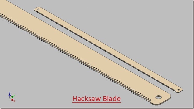
                          In this exercise we have used two 3D features → Extrude (Cut operation) and Rectangular Pattern.

                          Here a pre constructed part ‘Blade’ is taken from the model ‘Hacksaw’. 

                          download-Link 


                          Click the following link to get the model file: - http://bit.ly/2ooUYmN 


                           Transcription of Video

                          1. Open the Blade (.ipt) file.
                          2. A pre constructed Blade part file is visible in isometric view.
                          3. Select blue face of the Blade.
                          4. When the mini-toolbar appears, click the third button on the right, labeled with the tooltip Create Sketch.
                          5. Now we are in the sketch environment.
                          6. Take the project of the model by using Project Cut Edges tool.
                          7. Select all the sketches in the design window and convert them into construction geometry.
                          8. Create tooth profile with the help of line tool.
                          9. Now the sketch is complete.
                          10. Finish the 2D sketch.
                          11. Select any line of the enclosed profile, the mini-toolbar appears in the graphics window.
                          12. Click the Create Extrude icon.
                          13. It will automatically select the tooth profile.
                          14. Extrude dialog box is visible in the design window.
                          15. In the Extents field, select ‘All’ option from the drop down list.
                          16. It will automatically select the ‘Cut’ operation.
                          17. Click OK to create the feature.
                          18. Click the ‘Rectangular Pattern’ icon on the Pattern panel of 3D Model tab.
                          19. Rectangular Pattern dialogue box is visible in the graphics window.
                          20. Features button is active by default.
                          21. Select Extrusion3 from the browser bar.
                          22. Right click in the graphics window and choose Continue.
                          23. Select horizontal edge of the blade parallel to X Axis to define the direction of pattern.
                          24. Choose the Flip button to reverse the direction.
                          25. Set the column count to 192.
                          26. Set the column spacing to 0.0625 inch.
                          27. Now the preview of pattern is visible.
                          28. Click OK to execute the Rectangular Pattern Feature.
                          29. Right click the Rectangular Pattern2 in the browser bar, and then select Show Dimensions.

                          Application of ‘Text’ tool and ‘Emboss’ tool-Autodesk Inventor 2013 (with caption and audio narration)

                          Application of ‘Text’ tool and ‘Emboss’ tool

                          Serial No. 192

                          Application of ‘Text’ tool and ‘Emboss’ tool-Autodesk Inventor 2013 (with caption and audio narration)

                          In this exercise a pre constructed part file ‘Anvil’ is used.

                          download-Link 


                          Click the following link to get the model file: - http://bit.ly/2nJyMTG


                           Transcription of Video

                          1. Open the Anvil (.ipt) file.
                          2. At present a pre constructed part file of ‘Anvil’ is visible in the isometric view.
                          3. Create a new sketch on the blue face of the Anvil with the help of ‘Create 2D Sketch’ tool.
                          4. Take the project of the model by using ‘Project Cut Edges’ tool.
                          5. Select the projected model edges in the design window and convert them into construction geometry.
                          6. Start the ‘Text’ tool from the Draw panel of the Sketch tab.
                          7. In the graphics window, click to place the insertion point for the text box and drag to define the area of the text box.
                          8. Format Text dialogue box is visible in the graphics window.
                          9. In the ‘Format Text’ dialogue box, enter the text ANVIL in the specified area.
                          10. Select text and choose Center Justification and Middle Justification in the ‘Style’ option.
                          11. Enter the value 0.8 in the ‘Size’ field.
                          12. Change the text colour to Red.
                          13. In the ‘Font’ field, select ‘Calibri’ font from the drop down list.
                          14. Click OK to place the Text.
                          15. Right click in the graphics window and click OK to finish the command.
                          16. Apply Vertical constraint and Coincident constraint on the text to position it properly.
                          17. Finish the 2D sketch.
                          18. Activate the ‘Emboss’ tool from the Create panel of the 3D Model tab.
                          19. Emboss dialogue box is visible in the design window.
                          20. The profile selection is activated by default.
                          21. Select text as profile.
                          22. In the ‘Depth’ field enter the value 0.25 inch.
                          23. Change the direction of the feature by clicking the flip direction button.
                          24. Click OK to execute the Emboss feature.
                          25. Select the Emboss feature in the browser bar and activate the ‘Adjust’ tool from the ‘Quick Access Tool Bar’.
                          26. Adjust the appearance tinting of the feature and click OK to apply.

                          Monday, January 6, 2014

                          Application of ‘Extrude’ tool (Join operation) Autodesk Inventor 2013 (with caption and audio narration)

                          Application of ‘Extrude’ tool (Join operation)

                          Serial No. 191

                          Application of ‘Extrude’ tool (Join operation) Autodesk Inventor 2013 (with caption and audio narration)


                           download-Link 


                          Click the following link to get the model file: - http://bit.ly/2omKELY


                          Transcription of Video

                          1. Open the Part1 file.
                          2. A pre constructed sketch1 is visible in the design window.
                          3. Double click the Sketch1 in the browser bar.
                          4. Take the Offset of sketch, of the value 1/4 inch inside the enclosed profile.
                          5. Activate the extrude command from the marking menu.
                          6. Extrude dialogue box is visible in the design window.
                          7. The Profile selection button is active by default.
                          8. Select the profile enclosed by the yellow sketch and enter the distance value 3/8 inch.
                          9. Click OK to apply the extrude feature.
                          10. Open the visibility of Sketch1.
                          11. Activate the Extrude command once again from the Create panel.
                          12. Select the profile enclosed by the yellow lines and extrude it 1 inch in upward direction.

                          Sunday, January 5, 2014

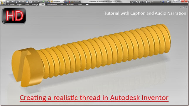
                          Creating a Realistic Thread (Autodesk Inventor 2013)

                          Creating a realistic thread in Autodesk Inventor
                          Video Tutorial with caption and audio narration
                           
                          The Screw file displayed in the video is taken from our model ‘Knob of Switch’.


                          First of all get the model files required to complete this tutorial by visiting the following link:- http://bit.ly/32leYVx 


                          Transcription of Video

                          1. Open the part file of Screw.
                          2. Select the 'Thread' tool in the Modify panel of 3D Model tab.
                          3. 'Face' selection button is automatically activated in the Thread dialogue box.
                          4. Select blue cylindrical face of the Screw.
                          5. Click the Specification tab, here it has automatically detected features/values like 'Thread Type', 'Size', 'Designation', 'Class' and 'Right Hand thread'.
                          6. If anyone wants to change the properties/features, it can be edited very easily.
                          7. Click OK to apply the thread feature.
                          8. Select the 'Thread Modeler' tool in the Thread Modeler panel of Tools tab.
                          9. Select Thread feature in the Browser Bar.
                          10. The Thread Modeler tool has automatically detected the pitch of the thread in the Thread Modeler Control dialogue box.
                          11. Click OK to apply realistic thread on the screw.
                          .....................................................................................................................................................
                          Visit Autodesk exchange Apps site on the following link to get  the ‘Thread Modeler Tool’ which is an external application utilized with the software :-

                          Friday, January 3, 2014

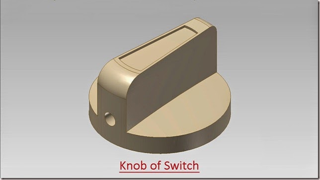
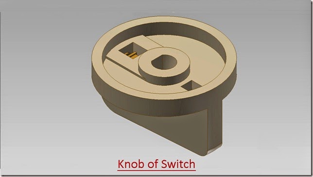
                          Knob of Switch-Autodesk Inventor 2013 (with caption and audio narration)

                          Knob_1 


                          Knob_2

                          Serial No. 184

                          Knob of Switch-Autodesk Inventor 2013 (with caption and audio narration)

                          download-Link 


                          Click the following link to get the model file: - http://bit.ly/2nI2Q2o


                           Transcription of Video

                          Modelling a ‘Knob of Switch’ (Autodesk Inventor 2013)

                          1. Open a New Standard (in).ipt file.
                          2. Create a new 2D sketch on the XY Plane.
                          3. Draw a circle of 1 ¾ inch diameter, coincident with the auto projected part origin.
                          4. Click Finish 2D Sketch command from the marking menu to exit the sketching mode.
                          5. Activate the ‘Extrude’ Command.
                          6. It will automatically select the circle as profile.
                          7. Enter the extrusion value ¼ inches and click OK.
                          8. Change the colour of the model to ‘Flaked Reflective – Beige’.
                          9. Save the file with the name ‘Knob of Switch’.
                          10. Change the view of the model by using View Cube.
                          11. Set the view as Home View by clicking the toggle next to View Cube.
                          12. Start a new sketch on the top face of the model.
                          13. Take the project of circular edge and Y Axis.
                          14. Convert this vertical line and circle into construction geometry.
                          15. Draw an arc over the projected edge of the model with the help of Centre Point Arc tool.
                          16. Apply a Coincident Constraint between mid-point of Arc and projected Y Axis line.
                          17. Give a linear dimension 1/4 inch between both the end points of the arc.
                          18. In the same way, draw another centre point arc as displayed.
                          19. Apply a Coincident Constraint between mid-point of arc and Y Axis.
                          20. Give a linear dimension 1/2 inch between both the end points of the arc.
                          21. Finish the sketch.
                          22. Create a new Work Axis on the one end of the arc, parallel to Z Axis of the model.
                          23. Create a new Work Point at the intersection of Work Axis 1 and bottom circular edge of the model.
                          24. Create a new work plane by using Three Point work plane tool.
                          25. Close the visibility of Work Point1 and Work Plane1.
                          26. Start a new sketch on this work plane.
                          27. Take the project of the model by using Projected Cut Edges tool.
                          28. Draw two vertical lines on both the end points of the top projected edge of the model.
                          29. And apply dimension 1 inch on these two lines.
                          30. Close the profile by using line tool.
                          31. Convert the sketches into construction geometry which are presently not in use.
                          32. Exit from the sketching environment.
                          33. Create another Work Axis on the second end point of the arc, parallel to Z Axis of the model.
                          34. Create another Work Point at the intersection of Work Axis 2 and bottom circular edge of the model.
                          35. Create a new work plane by using Three Points work plane tool.
                          36. Start a new sketch on this work plane.
                          37. Take the project of the model by using Projected Cut Edges tool.
                          38. Draw two vertical lines on both the end points of the top edge of the model.
                          39. And apply dimension 1 inch on these two lines.
                          40. Close the profile by using line tool.
                          41. Convert the sketches into construction geometry which are presently not in use.
                          42. Exit from the sketching environment.
                          43. Create another 3 Point work plane on the top end points of these lines.
                          44. Create a new sketch on this work plane.
                          45. Take the project of both arcs on this work plane.
                          46. Finish the sketch.
                          47. Start the Loft tool.
                          48. First select both the closed sketch profiles in the design window.
                          49. Then select four arcs as rails.
                          50. Click OK to create the Loft feature.
                          51. Create a new sketch on the top face of the model.
                          52. Take the project of top face of model by using Project Geometry tool.
                          53. Create a new sketch profile with the help of Offset tool.
                          54. Affix offset distance 1/32 inch between the lines.
                          55. Take the offset of upper and lower segment of arc.
                          56. Affix offset distance 5/16 inch between the arcs.
                          57. Snap the end points of arcs with the adjacent lines by using coincident constraint tool.
                          58. Erase the extra lines and arcs with the help of Trim tool.
                          59. Finish the 2D sketch.
                          60. Cut the enclosed area (defined by Sketch6) 1/32 inch towards downward direction by using Extrude Command.
                          61. Pick up the Fillet tool.
                          62. Select this circular edge of the top face, enter the value 1/4 inch in the Radius input box and click OK.
                          63. Apply another fillet of value 1/8 inch on the opposite side of the previous circular edge.
                          64. Rotate the model by using View Cube.
                          65. Create a new sketch on the bottom face of the model.
                          66. Take the project of bottom face of the model with the help of Project Geometry tool.
                          67. Create a new circle with the help of Offset tool.
                          68. Affix offset distance 1/8 inch between these two circles.
                          69. Finish the sketch.
                          70. Cut the enclosed area (defined by Sketch7) 3/16 inch towards downward direction by using Extrude Command.
                          71. Create a new sketch on the inner circular face of the model.
                          72. Draw a circle of diameter 5/8 inch and extrude this circle to 1/8 inch.
                          73. Create a new sketch on the YZ Plane of Knob-Switch.
                          74. Right click in the design window and select Slice Graphics command.
                          75. Take the project of Z Axis of the model and outer vertical edge.
                          76. Select both the vertical lines and change their colour to white.
                          77. Draw a horizontal line.
                          78. Place dimension ¼ inch between bottom edge of the model and horizontal line.
                          79. Select both the vertical lines and convert them into construction geometry.
                          80. Draw a vertical line of 1/32 inch length over the projected Z Axis of the model.
                          81. Draw an arc coincident with these two points with the help Three Point Arc tool.
                          82. Create another horizontal line and apply a tangent constraint between arc and this line.
                          83. Activate the Revolve tool from the right click context menu.
                          84. It will automatically select the sketch profile.
                          85. Click on this line to specify the axis of revolution and click on green checkmark.
                          86. A smooth oval face is created.
                          87. Rotate the model on the back side.
                          88. Create a new sketch on the blue circular face.
                          89. Draw a circle of diameter 5/16 inch, coincident with the centre point of the model.
                          90. Finish the sketch.
                          91. Create a new work plane, 5/8 inch downward from the blue face.
                          92. Create a new sketch on this new work plane.
                          93. Draw a circle of diameter 3/16 inch, coincident with the centre point.
                          94. Finish the sketch.
                          95. Pick up the Loft tool.
                          96. Select upper and lower circles in the design window.
                          97. Click Cut option in the loft dialogue box.
                          98. Click OK to create the loft feature.
                          99. Align the model in the desired position by using View Cube.
                          100. Create a new sketch on the blue circular face.
                          101. Take a project of inner circle and convert it to construction geometry.
                          102. Draw a line of length 3/16 inch parallel to X Axis.
                          103. Snap one end point of line on the circle with the help of coincident constraint tool.
                          104. Draw an arc between both the end points of the line by using Centre Point Arc tool.
                          105. Finish the 2D sketch.
                          106. Create a new sketch on the YZ Plane of the Knob.
                          107. Right click in the design window and select Slice Graphics command.
                          108. Take the project of the model by using Projected Cut Edges tool.
                          109. Select all the sketches and convert them into construction geometry.
                          110. Draw a line of the length 3/16 inch, along the slant edge of the taper hole.
                          111. Activate the Sweep tool from the right click context menu.
                          112. It will automatically select sketch as profile and taper line as path for sweep.
                          113. Click OK to create the sweep feature.
                          114. Create a new sketch on the blue circular face.
                          115. Take the project of the model by using Project Cut Edges command.
                          116. Right click in the design window and select Slice Graphics command.
                          117. Draw two vertical lines on the opposite quadrants of the circle.
                          118. Extrude this enclosed profile 1/32 inch.
                          119. Create a new sketch once again on the blue circular face.
                          120. Take project of the model by using Project Cut Edges tool.
                          121. Take the project of Y Axis of the model by using Project Geometry tool.
                          122. Select all the sketches and convert them into construction geometry.
                          123. Activate the Slice Graphics command.
                          124. Draw a vertical line between Point1 and Point2.
                          125. And convert this line into construction geometry.
                          126. Create a rectangle of dimension 3/16 inch x 5/16 inch, on the midpoint of the vertical line with the help of ‘Three Point Centre Rectangle’ tool.
                          127. Finish the 2D sketch.
                          128. Open the visibility of Work Plane4.
                          129. Create a new sketch on this Work Plane.
                          130. Click Visual Styles icon from the Appearance panel of the View tab.
                          131. Select Wireframe option.
                          132. Take the project of centre point of the rectangle.
                          133. Activate the Slice Graphics command.
                          134. Draw a Three Point Centre Rectangle of dimension 1/8 inch x 5/24 inch on this point.
                          135. Finish the 2D sketch.
                          136. Pick up the Loft tool.
                          137. Select upper and lower rectangles in the design window.
                          138. Click Cut option in the loft dialogue box.
                          139. Click OK to create the loft feature.
                          140. Create a new sketch on the blue selected face.
                          141. Take project of the model by using Project Cut Edges tool.
                          142. Take the project of Y Axis of the model by using Project Geometry tool.
                          143. Select all the sketches and convert them into construction geometry.
                          144. Activate the Slice Graphics command.
                          145. Draw a vertical line between Point1 and Point2.
                          146. And convert this line into construction geometry.
                          147. Create a square of side 1/4inch, on the midpoint of the vertical line with the help of ‘Three Point Centre Rectangle’ tool.
                          148. Finish the sketch.
                          149. Create a new work plane, 17/32 inch downward from the blue face with the help of ‘Offset from Plane’ tool.
                          150. Create a new sketch on this work plane.
                          151. Click Visual Styles icon from the Appearance panel of the View tab.
                          152. Select Wireframe option.
                          153. Take the project of centre point of the rectangle.
                          154. Activate the Slice Graphics command.
                          155. Draw a square of side 1/6 inch on this point by using ‘Three Point Centre Rectangle’ tool.
                          156. Finish the 2D sketch.
                          157. Pick up the Loft tool.
                          158. Select upper and lower rectangles in the design window.
                          159. Click Cut option in the loft dialogue box.
                          160. Click OK to create the loft feature.
                          161. Create a new work plane on Point1 which is parallel to the XY plane of the model.
                          162. Create a new work plane tangent to blue face of the model and parallel to XZ Plane with the help of ‘Tangent to Surface and Parallel to Plane’ command.
                          163. Create a new sketch on this work plane.
                          164. Take the project of Z Axis of the model and Work Plane7 of the model.
                          165. And convert them into construction geometry.
                          166. Draw a circle of diameter 3/16 inch whose centre lies on projected Z axis of the model.
                          167. Apply a tangent constraint between circle and projected edge of Work Plane7.
                          168. Finish the 2D sketch.
                          169. Activate the ‘Extrude’ Command.
                          170. It will automatically select the circle as profile.
                          171. Select Cut option to remove the material.
                          172. In the ‘Extents’ drop down of Extrude dialogue box, select ‘To’ option.
                          173. Select XZ Plane of the model to specify end of extrude feature.
                          174. Click OK to create the feature.