Friday, February 21, 2014

Tub-Rectangular through Sheet Metal-Autodesk Inventor 2013 (with caption and audio narration)

Tub-Rectangular through Sheet Metal

Serial No. 186

Tub-Rectangular through Sheet Metal-Autodesk Inventor 2013 (with caption and audio narration)

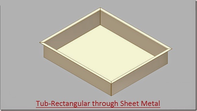
In this  video we will create a rectangular tub using sheet metal features (Face tool and Flange tool).


download-Link 


Click the following link to get the model file: - http://bit.ly/2ofTr23


 Transcription of Video

  1. Create a new Sheet Metal (in).ipt part file.
  2. Go on the ribbon > Setup panel > click Sheet Metal Defaults icon.
  3. The Sheet Metal Defaults dialogue box will be opened in the graphics window.
  4. Uncheck the ‘Use Thickness from Rule’ option to specify the thickness value 1/16 inch manually.
  5. Create a new sketch on the XY Plane.
  6. Draw a rectangle of dimension 32 ¼ inch x 27 inch with the help of ‘Three Point Centre Rectangle’ tool.
  7. Exit from the sketching environment.
  8. Activate the ‘Face’ tool from the marking menu.
  9. The sketch profile will be automatically selected.
  10. Click OK to apply face feature.
  11. Save the file with the name 'Tub (Rectangular)'.
  12. Change the colour of the model to ‘Flaked Reflective – Beige’.
  13. Activate the ‘Flange’ tool from the marking menu.
  14. On the Shape tab, click the ‘Loop Select Mode’ and click the bottom edge of the part.
  15. A preview of flange is visible in the graphics window.
  16. Click the Flip Direction button in the Height Extents field.
  17. And set the height extents value to 6 3/16 inch.
  18. Click OK to create the new flanges.
  19. Activate the ‘Flange’ tool once again.
  20. And select the four outer edges of the part.
  21. Fill the value 1 1/16 inch in the height extents field.
  22. Switch to the Corner tab, ‘Apply Auto-Mitering’ option is checked by default.
  23. Uncheck the Auto Mitering option to see the effect.
  24. Click OK to create the new flanges.
  25. Go on the ribbon > Flat Pattern panel > click Create Flat Pattern icon to generate the flat pattern of the model.
  26. Double-click the ‘Folded Model icon at the top of the Model browser to return to the folded model.

Thursday, February 20, 2014

Defining and Saving a Custom (Isometric) View in Creo Parametric 2.0

Defining and Saving a Custom (Isometric) View in Creo Parametric


In this tutorial you will see how to utilize the View Manger Tool to save a custom view and to navigate precisely in the graphics window.


Transcription of Video

  1. Click the View Manager Tool to display its dialogue Box.
  2. At present Orient tab is active. From here different type of views can be set and created/deleted.
  3. Here create a new view named Isometric View.
  4. Type the name and click the middle mouse button.
  5. Now Re-define this view.
  6. Orientation dialogue box will be opened.
  7. From here define the orientation of the model by specifying the Front and Top reference of the model.
  8. Switch to Dynamic Orient Tab.
  9. Here you can see Pan, Zoom and Spin navigation tools that are used to adjust the view of the graphic window. You can drag the slider or fill a precise value to operate them.
  10. Now spin the model 45° vertically and 30° horizontally.
  11. Hit Ok to exit.
  12. Now you can switch between the different views and set the view of your choice at any time.

Note :--

That was a manual way to set up Isometric View in Creo Parametric. But by watching this video you learned to utilize View Manager Tool, Re-orient Tool and other navigation tools.
To set up Isometric View by default in Creo Parametric go options--Model Display--Model orientation and select Isometric in the dropdown of Default Model Orientation.

Tuesday, February 18, 2014

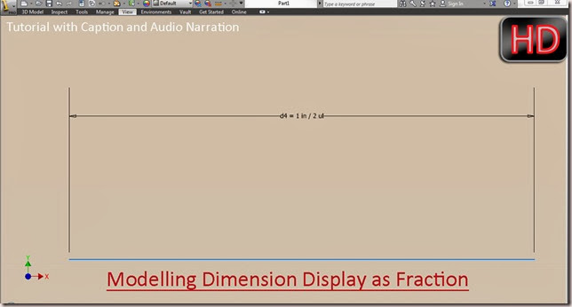
Customising the Modelling Dimension (as fraction) Display in Autodesk Inventor 2013

Customising the Modelling Dimension Display in Autodesk Inventor

Video Tutorial with caption and audio narration

This video will display how to set the dimension as fraction while working in 2D sketching environment.


Transcription of Video

  1. Visit to Tools Tab―Option Panel―Documents Settings, then in the Documents Setting dialogue box switch to Units Tab.
  2. In this tab, under the Modelling Dimension Display settings select the radio button of 'Display Dimension as Expression' and click apply to get the desired result.
  3. This setting can be also done by the marking menu.

Thursday, February 13, 2014

Tuesday, February 11, 2014

Fabrication of frame for Table by Frame Generator (Autodesk Inventor 2013)

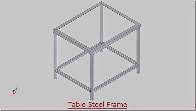
Table-Steel Frame

In this exercise utilization of Frame Generator tools is displayed to create a frame for a steel table. Application of Insert Frame Member, Miter Corners, Trim and Extend To Face and Notch Tools are displayed in the video.

 download-Link

First of all get the model files required to complete this tutorial by visiting the following link: - http://bit.ly/33lwB91


Transcription of Video

  1. Open the ‘Table-Steel Frame’ assembly file.
  2. A pre-constructed Part1 file is already placed in this assembly is to be used as skeleton for creating frame members.
  3. Switch to Design tab and activate the ‘Insert Frame Members’ tool from the Frame panel.
  4. The Insert Frame dialogue box is visible in the graphics window.
  5. In the Placement field ‘Insert Members on Edges’ selection button is activated by default.
  6. Select ‘ANSI AISC HSS (Square) – Square tube’ in the Family menu.
  7. Select the standard frame size {(1-1/4)x(1-1/4)x(1/8)} from the Size menu.
  8. Select the four vertical edges and four blue horizontal lines of the model for generating the frame members.
  9. A preview of frame members is visible in the graphics window.
  10. Click OK.
  11. Click OK once again in the Create New Frame dialog box.
  12. The Frame Member Naming dialog box displays. This dialog box is used to change member display names, member file names, and locations.
  13. Click OK without making any changes.
  14. Activate the ‘Insert Frame Members’ tool once again.
  15. Select ‘ANSI L (Equal angles) – Angle Steel from the Family menu.
  16. Select the standard frame size {L(1.5)x(1.5)x(3/16)} from the Size menu.
  17. Select one edge on the top face of skeleton.
  18. Enter the value 90 degree in the Angle field.
  19. Enter the value (-1/16) inch in the Vertical Offset field.
  20. Enter the value 9/16 inch in the Horizontal Offset field.
  21. Click Apply.
  22. In the same way add 3 more angle iron on the top edge of the skeleton.
  23. Close the visibility of Part1:1 from the Browser Bar.
  24. Activate the ‘Miter Corners’ tool from the Frame panel of Design tab.
  25. Miter dialogue box is visible in the graphics window.
  26. ‘Miter Cut at both sides’ is selected by default.
  27. Select the first and second frame members as shown.
  28. Click Apply to create the miter.
  29. Similarly create 3 more miter joints on the remaining frame members.
  30. Click OK to close the dialogue box.
  31. Activate the ‘Trim and Extend to Face’ tool from the Frame panel of Design tab.
  32. Trim-Extend to Face dialogue box is visible in the graphics window.
  33. ‘Frame Member’ is selected by default.
  34. First select the component to be trimmed, which is Square tube.
  35. Second select the component that will be used as reference, which is the face of the Square tube.
  36. Click Apply.
  37. Repeat the same steps as shown.
  38. Close the Trim to Frame dialogue box.
  39. Double click the Frame0001 in the browser bar to edit it.
  40. Activate the ‘Analyze Interference’ command from the Interference panel of Inspect tab.
  41. Analyze Interference between angle iron and frame leg.
  42. Interface has been detected.
  43. Click OK to close the Interference Detected dialogue box.
  44. Return back to the assembly environment.
  45. Activate the ‘Notch Frame Member’ tool from the Frame panel of Design tab.
  46. Notch dialogue box is visible in the graphics window.
  47. ‘Frame Member’ is selected by default.
  48. The first selection is the component to cut and the second selection is the cutting tool.
  49. First select the tube, as shown.
  50. And then select the angle iron to use it as the cutting tool.
  51. Click Apply.
  52. Now check the Analyze Interference once again.
  53. There was no interference detected.
  54. Isolate the frame to check the effect of notch feature more clearly.
  55. Repeat the same steps as shown.
  56. Now the frame structure is complete.
  57. Save the Assembly.

Monday, February 10, 2014

Setting up a Hinge (Pin) Mechanism in Creo Parametric 2.0

Setting up a Hinge (Pin) Mechanism in Creo Parametric 2

Video Tutorial with caption and audio narration
..............................................................................

In this Assembly Modelling Tutorial of Creo Parametric a mechanism of a Hinge is created by using predefined Pin constraint that is available in the software. First of all, the previously created components of Hinge will be placed in the assembly and then mates will be applied to set up the mechanism. To animate this mechanism read a related blog post by me Animation of Hinge || Using Creo Mechanism.

 download-Link


Click the following link to get the model file: -http://bit.ly/2nzc29d


Transcription of Video

  1. We have following components of Hinge, which we will place in an assembly.

  2. Later we will test its mechanism with the help of Drag Component tool.

  3. Create a new assembly with default template.

  4. Give it a name Hinge.

  5. Place the part_1 in the assembly.

  6. Drag the part so that you can see the Datum Planes of Assembly clearly.

  7. Constraint Type is set to Automatic by default.

  8. Apply a constraint between Right Datum plane of assembly and Right Datum Plane of part_1.

  9. Add a new constraint and select Front Datum Planes of assembly and Front Datum Planes of part_1 to apply a coincident constraint automatically.

  10. In the same way apply a coincident constraint between Top Datum Plane of Assembly and Top Datum Plane part_1.

  11. Now STATUS area indicates that the component is fully constrained in the assembly.

  12. Click the green check mark to apply and save the changes.

  13. Now place the part_3 in the assembly.

  14. Drag the part_3 and re-align it in the graphic window.

  15. Select the axis of part_1 and axis of part_3 to apply a coincident constraint between them.

  16. Drag the part_3 in the graphics window and apply a coincident constraint between its front datum plane and Front datum plane of the assembly.

  17. Now the component is fully constrained in the assembly.

  18. Place part_2 in the assembly.

  19. Rotate the part and re-align it.

  20. Select a predefined constraint named Pin.

  21. Select the axis of part_2 and axis of part_3 to apply a coincident constraint between them.

  22. Now click the Placement tab and define the reference of translation.

  23. The STATUS area indicates the Connection Definition is complete.

  24. Click the green check mark to apply and save the changes.

  25. Give away different colours to the parts of the assembly so that they can be recognized easily.

  26. Align the model in an isometric view using Re-orient tool.

  27. Clear the screen by closing the visibility of Datum planes, axis, points and everything else.

  28. Select the top face of part_2 and drag it with the help of Drag Component tool to check the mechanism of Hinge assembly.

  29. Only part_2 of Hinge can be moved because we applied a pre-defined Pin constraint on it.

  30. Re-generate the file and save it.

Saturday, February 8, 2014

Tray-Autodesk Inventor 2013 (with caption and audio narration)

Tray_1

Tray_2

Serial No. 101

Tray-Autodesk Inventor 2013 (with caption and audio narration)

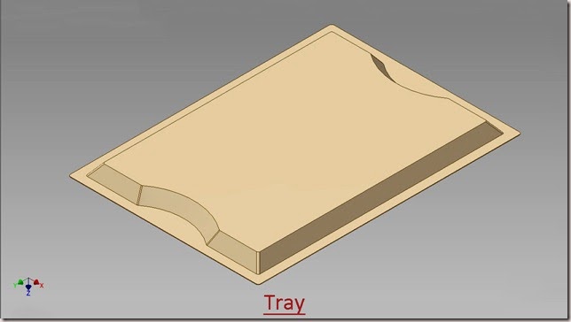
In this exercise, a Tray will be created by using surface features of Autodesk Inventor.  First of all, a pre-constructed sketch will be imported and later Boundary Patch, Surface Loft, Stitch Surface and Thicken /Offset tools will be utilized to complete the model.


download-Link 


Click the following link to get the model file: - http://bit.ly/2mCzuSL


Transcription of Video

  1. Create a new Standard(in).ipt file .
  2. Import the ‘Base Sketch’ as a derived component, required for creating the model.
  3. Activate the Derive Component Tool from the Create panel of 3D model tab.
  4. Select ‘Base Sketch of Tray’ file and open it.
  5. Derived Part dialogue box is visible in the design window.
  6. Derive the sketches from the file.
  7. Click Ok to execute the command.
  8. Two sketches (one for top face and the other for back face) have been imported from the file ‘Base Sketch of Tray’.
  9. Activate the ‘Boundary Patch’ tool from the Surface Panel of 3D Model Tab.
  10. Boundary Patch dialogue is visible in the graphics window.
  11. Select the top sketch of the model.
  12. Click Ok to create the Boundary Patch Feature.
  13. Activate the Boundary Patch Tool once again.
  14. Select the bottom sketch profile of the model to create another boundary patch feature.
  15. Activate the Loft tool from the Create panel of 3D Model tab.
  16. The Loft dialogue box is visible in the graphics window.
  17. Select the internal edge (loop) of Boundary Patch1 and outer edge (loop) of Boundary Patch2 to create a new 3D surface.
  18. A preview of loft is visible in the graphics window.
  19. Click OK to execute the loft feature.
  20. Activate the ‘Stitch Surface’ tool from the Surface Panel of 3D Model Tab.
  21. Stitch dialogue box is visible in the graphics window.
  22. Surfaces selection is active by default.
  23. Right click in the graphics window and choose ‘Select All’ option from the context menu to select all the surfaces at once.
  24. A preview of stitch is visible in the graphics window.
  25. Click Apply to stitch all the surfaces.
  26. Stitch Surface tool combined all the surfaces into a single surface.
  27. Activate the ‘Thicken/Offset’ tool from the Surface Panel of 3D Model Tab.
  28. Thicken/Offset dialogue is visible in the graphics window.
  29. Face radio button is selected by default.
  30. Click the Quilt radio button to select all the surfaces of the model at once.
  31. And select the surface in the graphics window.
  32. Enter the value 1/32 inch in Distance field to specify the thickness of the model.
  33. A sheet along with its thickness is now visible in the preview.
  34. Click OK to execute the Thicken feature.
  35. Close the visibility of Stitch Surface1 from the Browser Bar.
  36. Change the model colour to ‘Flaked Reflective – Beige’.
  37. Apply a fillet of 1/8 inch on the following edges of the model.
  38. Save the part file with the name ‘Tray’.

Thursday, February 6, 2014

Creating a Notch of Mug-Autodesk Inventor 2013 (with caption and audio narration)

Creating a Notch of Mug

Serial No. 201

Creating a Notch of Mug-Autodesk Inventor 2013 (with caption and audio narration)

In this exercise, we are using a partially constructed model of ‘Mug-Plastic’. We will take help of 2D&3D sketches, work planes, work points, 3D surfaces by using boundary patch tool and sculpt feature to complete the model.

 download-Link


Click the following link to get the model file: - http://bit.ly/2osv0P9


Transcription of Video

  1. Open the file of ‘Mug-Plastic’.
  2. At present a surface is visible in the design window which is created with the help of Revolve Tool.
  3. Open the visibility of Sketch1 from the browser bar.
  4. Create a new work plane on this point, perpendicular to Y Axis of the model.
  5. Auto-Resize this work plane.
  6. Create a sketch on the newly created Work Plane11.
  7. Take the project of XY plane and top circular edge of the model with the help of Project Geometry Tool.
  8. Convert all the projected edges into construction geometry.
  9. Close the visibility of Sketch1 from the browser bar.
  10. Now proceed ahead and draw a triangular shape geometry intact with the projected circular edge of the model.
  11. The sketch is complete, so exit from the sketching environment.
  12. Create a new work plane, parallel to Work Plane11 at an offset distance of 1.25 inches in downward direction.
  13. Close the visibility of Work Plane11.
  14. Create a new sketch on Work Plane12.
  15. Take the project of the model by using Project Cut Edges tool.
  16. And take the project of XY Plane with the help of Project Geometry tool.
  17. Finish the 2D sketch.
  18. Create a work point at the intersection of this line and circle.
  19. In the same manner add three more work points at the vertices of the triangular shaped geometry.
  20. Close the visibility of Work Plane12 and Sketch22.
  21. Activate ‘New 3D Sketch’ command from the marking menu.
  22. Create a 3D Line between Work Point5 and Work Point6.
  23. Right click in the graphic window and finish the 3D sketch.
  24. In the same way, create a 3D Line between Work Point5 and Work Point7 in a new 3D sketch.
  25. At last connect the Work Point8 with the Work Point5 by following the same procedure.
  26. Close the visibility of all Work Points.
  27. Activate the ‘Boundary Patch’ tool from the Surface Panel of 3D Model Tab.
  28. Boundary Patch dialogue is visible in the graphics window.
  29. Select two 3D Lines and one edge of triangular shaped geometry for creating a new 3D surface.
  30. Click Ok to create the Boundary Patch Feature.
  31. Open the visibility of Sketch21 which is hidden under the Boundary Patch Feature.
  32. Activate the Boundary Patch Tool once again.
  33. This time select the edge of Boundary Patch4 and both visible lines to create another Boundary Feature.
  34. Activate the ‘Extend Surface’ tool from the drop down list of Surface panel.
  35. Extend Surface dialogue box is visible in the graphics window.
  36. Edges selection is active by default.
  37. Select this edge of Boundary Patch4 to extend the surface.
  38. Leave the value of Extents distance as it is and click Ok to execute the command.
  39. In the same manner Extend the other 3D surface created with the help of Boundary Patch5.
  40. Close the visibility of Sketch21.
  41. Open the visibility of Work Plane11.
  42. Activate the ‘Sculpt’ tool from the Surface Panel of 3D Model Tab.
  43. Sculpt tool dialogue box is visible in the graphics window.
  44. Surfaces selection is active by default.
  45. Right click in the graphics window and ‘Select All’ option from the context menu.
  46. A preview of sculpt is visible in the graphic window.
  47. Click OK to create the Sculpt feature.
  48. Sculpt feature combined all the surfaces into a solid body.
  49. Close the visibility of Work Plane11 and save the part file.
  50. Create a new sketch on the top face of the model.
  51. Convert the projected top edge of the model into construction geometry.
  52. Duplicate this enclosed profile by using Offset tool.
  53. And set the offset distance value 0.125 inch.
  54. Exit from the sketching environment.
  55. Activate the Extrude command from the marking menu.
  56. Enclosed profile is automatically selected in the graphics window.
  57. Drag the direction indicator in downward direction.
  58. Set the distance value 0.0625 inch on the mini tool bar.
  59. Select ‘Join’ operation.
  60. Click the green check mark to execute the extrude command.
  61. Rotate the model on the back side.
  62. Create a new sketch on this face.
  63. Duplicate the outer projected edge of the model by offset tool.
  64. Enter the offset distance value 0.0625 inch.
  65. Finish the 2D Sketch.
  66. Extrude this profile 0.1875 inch.
  67. Click Home View button over the View Cube.
  68. Activate the Shell tool from the Modify panel of 3D Model tab.
  69. Shell dialogue box is visible in the graphics window.
  70. Remove Faces selection option is activated by default.
  71. Select top face of the model to remove it.
  72. The preview of shell is visible in the graphics window.
  73. Set the Thickness value 0.0625 inch.
  74. Click OK to execute the Shell feature.
  75. Now the notch of Mug is complete.
  76. Inspect the model with the help of ‘Cross Section Analysis’ tool.
Application of ‘Loft’ tool Ex.2--Autodesk Inventor 2013 (with caption and audio narration)

Application of 'Loft' tool

Serial No. 200

Application of ‘Loft’ tool Ex.2--Autodesk Inventor 2013 (with caption and audio narration)

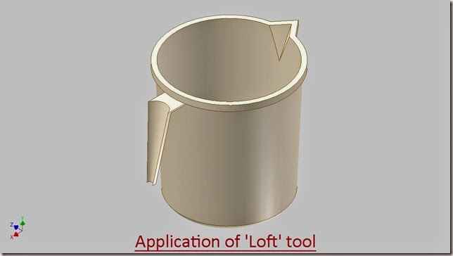
In this exercise, we are using a partially constructed model of ‘Mug-Plastic’. We will create a Handle on the curve surface of the model, for this we will add some 2D sketches, work planes and Loft feature.


download-Link 


Click the following link to get the model file: - http://bit.ly/2nNFfgo


 Transcription of Video

  1. Open ‘Mug-Plastic’ part file.
  2. Create a new work plane 0.25 inch below from the top face of the model.
  3. Create a new sketch for upper portion of handle on the newly created work plane.
  4. Right click in the graphics window and select Slice Graphics command.
  5. Take the project of the model by using Project Cut Edges tool.
  6. And with the help of Project Geometry tool, take the project of XY Plane.
  7. Select all the sketches in the design window and convert them into construction geometry.
  8. Now proceed further and draw a sketch with the given dimensions.
  9. Exit from the sketching environment.
  10. Close the visibility of Work Plane8 from the Browser Bar.
  11. Create another work plane named 9, 3 inch below from the top face of the model.
  12. Create a new sketch for lower portion of handle on Work Plane9.
  13. Close the visibility of work plane and activate the Slice Graphics command.
  14. Draw the sketch with the given dimensions.
  15. Now the sketch is complete.
  16. Finish the sketch.
  17. Activate the ‘Loft’ tool.
  18. Select the upper and lower sketch profiles in the graphics window.
  19. Preview of Loft is visible.
  20. Click OK to execute the loft feature.
  21. Open the visibility of Sketch17 from the Browser Bar.
  22. Create a new sketch on Work Plane8.
  23. Take the project of these two lines and arc.
  24. Draw a centre point arc between point1 and point2 (indicated by blue colour).
  25. Close the visibility of Sketch17 from the browser bar.
  26. Revert these two construction lines into regular lines.
  27. Exit from the sketching environment.
  28. Create a new work plane named 10, 0.0625 inch below from the top face of the handle.
  29. Auto-Resize the work plane.
  30. Create a new sketch on work plane 10.
  31. Activate the Slice Graphics command.
  32. Close the visibility of Work Plane10.
  33. Take the project of the model by using Project Cut Edges tool.
  34. And with the help of Project Geometry tool, take the project of XY plane.
  35. Convert all the sketches in the graphics window into the construction geometry.
  36. Draw the sketches as displayed.
  37. Finish the sketch.
  38. Activate the Loft tool once again.
  39. Select the upper and lower enclosed profiles, created over the handle.
  40. And click OK to execute the loft feature.
  41. Now most of the portion of the handle is complete.
  42. Save the part file.

Saturday, February 1, 2014

Double Sided Half V-Groove Weld Joint-Autodesk Inventor 2013 (with caption and audio narration)

Double Sided Half V-Groove Weld Joint

Serial No. 28

Double Sided Half V-Groove Weld Joint-Autodesk Inventor 2013 (with caption and audio narration)


download-Link 


Click the following link to get the model file: -http://bit.ly/2n4rHgu


Transcription of Video

  1. Create a New Standard (in).ipt file.
  2. Draw a new sketch on XY Plane.
  3. Draw a Rectangle of sides 1 inch and 1/8 inch with the help of ‘Three point Centre Rectangle’ tool.
  4. The center point of the rectangle should lie on the auto projected part origin.
  5. Take the project of X Axis of part file by using Project Geometry tool.
  6. Select all the sketches in the graphics window and convert them into construction geometry.
  7. Add two more lines in the sketch and apply Symmetric constraint between them.
  8. And apply 45 degree dimension between these two lines.
  9. Close the profile by using line tool.
  10. Finish the 2D sketch.
  11. Select any one of the line of enclosed profile, a mini-toolbar will appear in the graphics window.
  12. Click the ‘Create Extrude’ icon.
  13. Extrude dialogue box is visible in the graphics window.
  14. In the Extents field, select ‘Symmetric’ option.
  15. Fill the value 2inch in the distance input box.
  16. Click OK to create the extrude feature.
  17. Change the model colour to 'Flaked Reflective - Beige'.
  18. Save the part file with its default name (Part1).
  19. Close the part file.
  20. Create a New Standard (in).iam file.
  21. Place two instances of ‘Part1’ in the assembly with the help of ‘Place Component’ tool.
  22. Save the Assembly with the name ‘Double Sided Half V-Groove Weld Joint’.
  23. Click the ‘Rotate’ icon on the Position panel of Assemble tab.
  24. Select Part1:2 in the design window and rotate the part as displayed.
  25. Right click in the graphics window and click OK to close the tool.
  26. Activate the Constraint command from the marking menu.
  27. Place Constraint dialogue box is visible in the graphics window.
  28. By default ‘Solution Type’ is set to Mate, change it to Flush.
  29. Select the top face of both parts to apply a flush mate.
  30. Apply a Flush mate once again but this time select front face of both parts.
  31. Apply a Mate constraint between side edges of both parts.
  32. Now our assembly is fully constrained.
  33. There is no degree of freedom.
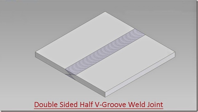
  34. To apply a weld between these parts convert the assembly into weldment , click the ‘Convert to Weldment’ icon, located on the Convert panel of Assemble tab.
  35. Click Yes button, when prompted that you will not be able to revert this data to a basic assembly.
  36. Convert to Weldment dialogue box is visible in the graphics window.
  37. Leave the default settings click and OK to close the dialogue box.
  38. Double-click the ‘Welds’ group in the browser to activate the weldment tools.
  39. Activate the ‘Groove Weld’ tool, located on the Weld panel of Weld tab.
  40. Groove Weld dialogue box is visible in the graphics window.
  41. Select the Full Face Weld check box in the Face Set 1 and Face Set 2 under the Bead box field.
  42. Click the Face Set 1 button.
  43. Select this face of the Part.
  44. Click the Face Set 2 button.
  45. Select this face of adjacent part.
  46. Click OK to create a groove weld between the both parts.
  47. In the same manner apply another groove weld over the rear side of the model.
  48. Save the Assembly.