Thursday, March 27, 2014

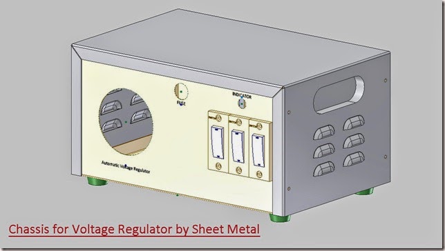
Chassis for Automatic Voltage Regulator by Sheet Metal (Autodesk Inventor 2013)

Chassis for Automatic Voltage Regulator by Sheet Metal _1

Chassis for Automatic Voltage Regulator by Sheet Metal _2

Serial No. 189

Chassis for Automatic Voltage Regulator by Sheet Metal (Autodesk Inventor 2013)

Inside this video, viewers will watch full detailed process of creating this model through Autodesk Inventor Software's Sheet Metal design functionality .

download-Link 

Click the following link to get the model file: - http://bit.ly/2omQj4E

Monday, March 24, 2014

Circular Tub through Sheet Metal-Autodesk Inventor 2013 (with caption and audio narration)

Circular Tub through Sheet Metal

Serial No. 188

Circular Tub through Sheet Metal-Autodesk Inventor 2013 (with caption and audio narration)

Inside this video, viewers will watch the full detailed process of creating this model through Autodesk Inventor Software's Sheet Metal design functionality.

download-Link 


Click the following link to get the model file: - http://bit.ly/2nJu6gA


Transcription of Video

  1. Create a new sheet metal part file with an English template.
  2. Go to Setup panel and activate Sheet Metal Defaults.
  3. Specify the thickness of the sheet manually and end the command.
  4. Create a new sketch over the XY plane.
  5. Take the project of Y Axis and convert this projected line into centreline.
  6. Draw a sketch along with dimensions by utilizing Line tool.
  7. Use constrains to position the geometry and fully constrain the sketch.
  8. The required sketch is complete, hence finish the sketch.
  9. Go to Create panel and activate Contour Roll tool.
  10. Profile geometry and rotation axis are automatically selected.
  11. Offset the material thickness to the other side of the selected profile.
  12. Fill up the Rolled Angle.
  13. Activate sweep the Contour Roll both side equally option.
  14. Terminate the command.
  15. Save the part file with the default name.
  16. Change the colour of the model to Flaked Reflective-Being.
  17. Activate Cross Section Analysis Tool to get the information about the interior of the part.
  18. This view provides a cutaway view of the part along XY plane.
  19. Now deactivate the command from the Browser Bar.
  20. Go to Flat Patten panel and activate Create Flat Pattern tool.
  21. Check the bend sequence of the part by activating the Bend Order Annotation command.
  22. Return back to folded Sheet Metal part.
  23. Save and close the file.
  24. Create a new assembly file with an English template.
  25. Place the previously created sheet metal part in the assembly.
  26. Save the assembly with the name ‘Circular Tub through Sheet Metal’.
  27. Create a new sheet metal part in the assembly using English template.
  28. Define XY Plane of the Assembly as the sketch plane for the base feature.
  29. Specify the thickness of the sheet by activating Sheet Metal Defaults command.
  30. Start a new sketch over the XY plane of the part.
  31. Take the project of Part 1 by using Project Cut edges command.
  32. Activate Project Geometry tool and take the project of Y axis.
  33. Convert all the projected lines into Construction Geometry.
  34. Finish the sketch and return back to assembly.
  35. Switch to View tab—Appearance panel and activate Half Section View along the XY plane of the assembly.
  36. Again edit the Part 2 and activate the previously created Sketch 1.
  37. Draw a sketch along with dimensions as displayed.
  38. The required sketch is complete so finish the sketch.
  39. Activate the Contour Roll tool.
  40. Profile geometry is automatically selected so define Y axis as axis of rotation.
  41. Offset the material thickness to both side of the selected profile.
  42. Activate sweep the contour roll both side equally option.
  43. The last applied Rolled Angle is filled up automatically.
  44. Execute the command.
  45. Change the colour of the part to Maple - Solid Natural Medium Gloss.
  46. Save the part file and return to assembly.
  47. In the assembly Half Section View is active, take a closer look of the assembly to get the information about the interior of the model.
  48. Switch to View tab and end the Half Section View command.
  49. Select the Part 2 in the browser bar and open it separately.
  50. Check the Flat Pattern of the model as well as Bend Order sequence.
  51. Close the part and return to assembly.
  52. At present there are degrees of freedom in the assembly.
  53. Apply a Mate constraint between Y Axis of Assembly and Y Axis of Part 2.
  54. Activate Flush Mate and click ‘Predict Offset and Orientation’ option.
  55. Select top face of Part 1 and top face of Part 2 and apply the flush mate.
  56. Now there is no degree of freedom left in the assembly.
  57. Switch to Inspect Tab and Analyze interface between the assembly parts.
  58. There were no interfaces detected.
  59. Save the file.

Tuesday, March 18, 2014

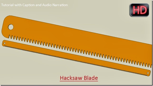
Modelling a Hacksaw Blade (Creo Parametric 2.0)

Hacksaw Blade

In this video tutorial creation of a Hacksaw Blade is displayed. Viewers will be able to watch application of many part modelling tools like Extrude, Round, Hole, Mirror and Pattern as well as 2D sketching techniques are also shown.


Transcription of Video

  1. Start a new part file from scratch and give it a name ‘Hacksaw Blade.’
  2. Select the Top Datum plane and create a new sketch on this plane.
  3. Click the Sketch View icon. This will orient the sketching plane parallel to the screen.
  4. Close the visibility of the Datum Planes, Axis and Points etc. to make the screen clear.
  5. Pick the Centre Rectangle tool from the Sketching panel.
  6. Draw a Rectangle and apply the dimensions as displayed.
  7. As soon as the new dimensions are applied the software will automatically adjust the view of design window so that the sketch can be seen clearly.
  8. Click green check mark to finish the sketch.
  9. Activate the Extrude Tool from the Shape Panel.
  10. Select the sketch and define the depth value.
  11. Select extrude both side of the sketch equally option and execute the command.
  12. Change the colour of the part according to your wish so that it can be acknowledged easily in the design window.
  13. Activate the Reorient tool and position the model in an isometric view using navigation tools.
  14. Save this view for future reference.
  15. Save the part file.
  16. Activate the Round Tool from the Engineering Panel.
  17. Select four outer edges of the model.
  18. Define the radius of the round and execute the command.
  19. Activate the Hole tool.
  20. Select the Top Face of the model to define the Placement Reference.
  21. Enter the Diameter Value for the drilled hole.
  22. Set the offset references of the hole and fill the corresponding offset values.
  23. Select through all option and execute the command.
  24. Open the visibility of Datum Planes.
  25. Select the Hole 1 in the Model Tree and activate the Mirror Tool from the Editing Panel.
  26. Select Right Datum Plane as Mirroring Plane and execute the command.
  27. Select the top face of the model and start a new sketch on this face.
  28. Specify two references for the sketch.
  29. Draw a sketch with the help of line tool as displayed.
  30. Apply the dimensions as displayed.
  31. Click green check mark to finish the sketch.
  32. Activate the Extrude Tool and select the sketch.
  33. Flip the Depth Direction.
  34. Select Remove Material option and Through all option.
  35. Click the green check mark to apply and save the changes.
  36. Select the Extrude 2 in the Model Tree and activate the Pattern Tool from the Editing Panel.
  37. Set Direction as the type of pattern.
  38. Select the front edge of the model to define the direction of the pattern.
  39. Enter the number of members to be patterned.
  40. Define the spacing between the pattern members.
  41. Click the green check mark to apply and save the changes.
  42. So fully developed model is visible in the graphics window.

download-Link


Get the finished model file by visiting the following link :--http://bit.ly/2odNPp1

Wednesday, March 5, 2014

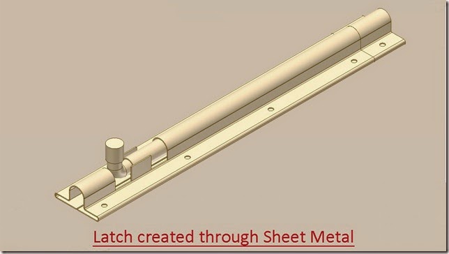
Latch created through Sheet Metal-Autodesk Inventor 2013 (with caption and audio narration)

Latch created through Sheet Metal

Serial No. 187

Latch created through Sheet Metal-Autodesk Inventor 2013 (with caption and audio narration)

In this video, the creation of an assembly of the latch is shown. First base body parts of the latch will be created using sheet metal template that will utilize Contour Flange, Cut and Mirror tools. Afterwards, a previously created part Sliding rod will be placed in the assembly to complete it.


download-Link 


Click the following link to get the model file: – http://bit.ly/2mRK1tf


 Transcription of Video

Latch created through Sheet Metal (Autodesk Inventor)

  1. Open the ‘Latch Body1’ part file.
  2. A ‘Base sketch of Latch’ is created in this file.
  3. Go on the ribbon > Setup panel > click Sheet Metal Defaults icon.
  4. Uncheck the ‘Use Thickness from Rule’ option to specify the thickness value 3/128 inch manually.
  5. Go on the ribbon > Create panel > click Contour Flange icon.
  6. The Profile selection button is active by default in the Contour Flange dialogue box.
  7. Select the sketch profile.
  8. A preview of contour flange is visible in the graphics window.
  9. The thickness of sheet should be inside of the sketch profile.
  10. Set the value 7 7/8 inch in the Distance field.
  11. Click OK to create the feature.
  12. Create a new sketch on the right face of the part.
  13. Take the project of this face by using Project Geometry tool.
  14. Convert the projected lines into construction geometry.
  15. Draw a rectangle with the given dimensions.
  16. Exit from the sketching environment.
  17. Go on the ribbon > Modify panel > click Cut icon.
  18. The sketch profile will be automatically selected.
  19. Choose ‘All’ option under the Extents field.
  20. Click OK to apply the cut feature.
  21. Create a new sketch on the selected face.
  22. Take the project of this edge and convert it to construction geometry.
  23. Draw a new line of length 9/16 inch.
  24. Apply a coincident constraint between midpoint of the line and midpoint of the projected line.
  25. Finish the 2D Sketch.
  26. Activate the Contour Flange tool once again.
  27. Select the line.
  28. Click more button to expand the dialogue box.
  29. Set the Width Extents type to ‘Distance’.
  30. Enter the value 0.35156 inch in Distance field.
  31. Click OK to create the new flange.
  32. Go on the ribbon > Pattern panel > click Mirror icon.
  33. Select the Contour Flange3 in the graphics window as feature to pattern.
  34. Click Mirror Plane button.
  35. In the Model browser, pick YZ plane under the Origin folder.
  36. Click OK to mirror the feature.
  37. Pick the ‘Corner Round’ tool from Modify Panel.
  38. And select these four corner edges of the part.
  39. In the Corner Round dialogue box, set the radius to 1/64 inch.
  40. Click OK to place the fillet.
  41. Go on the ribbon > Flat Pattern panel > click Create Flat Pattern icon to generate the flat pattern of the model.
  42. Activate the ‘Bend Order Annotation’ tool from the marking menu.
  43. The flat pattern will display numbers that represent the order in which the part would be folded.
  44. Right click in the graphics window; click OK to finish the bend order annotation command.
  45. Double-click the ‘Folded Model icon at the top of the Model browser to return to the folded model.
  46. Save the part file and close it.
  47. Start a new Standard (in) assembly.
  48. Place the ‘Latch Body1’ part file by using ‘Place Component’ tool.
  49. Save the assembly with the name ‘Latch’.
  50. Create a new component using sheet metal template with the name ‘Latch Body2’ in this assembly.
  51. Select back face of the Latch Body1 to define the sketch plane for the base feature of the new part.
  52. Open the visibility of ‘Base sketch of Latch’ in the Browser Bar.
  53. Create a new sketch on this face.
  54. Take the project of end points of the sketch and centre point of arc.
  55. Close the visibility of ‘Base sketch of Latch’ in the Browser Bar.
  56. Recreate the base sketch by joining these projected points.
  57. Activate the ‘Sheet Metal Defaults’ command.
  58. Uncheck the ‘Use Thickness from Rule’.
  59. Set the value 3/128 inch in the Thickness field.
  60. Activate the ‘Contour Flange’ tool.
  61. And select the sketch profile.
  62. Click the ‘Flip Side’ button to set the thickness of sheet inside of the sketch profile.
  63. Fill the value 7/8 inch in the ‘Distance’ field.
  64. Click OK to create the new flange.
  65. Return back to the assembly environment.
  66. Save the assembly.
  67. Open the ‘Latch Body2’ part file separately.
  68. Change the model colour to ‘‘Flaked Reflective - Beige’.
  69. Check the Flat Pattern and Bend sequence of the folded sheet.
  70. Place the ‘Sliding rod’ in the Assembly.
  71. Apply an axis mate between Sliding rod and Latch Body1.
  72. Double click the ‘Latch Body1’ in browser bar to edit it.
  73. Start a new sketch on this face of the part.
  74. Take the project of the face and draw a line connecting the mid points of the projected edges.
  75. Convert all the sketches into construction geometry.
  76. Create a circle over this line of 1/8 inch diameter that would be 3/8 inch away from the front face of the model.
  77. Finish the sketch and start the Cut Tool from modify panel.
  78. Select All option in the dropdown of Extents and apply the command.
  79. Create 3 more identical holes at an offset distance of 2 3/8 inch between each hole on the same face of the model by using ‘Rectangular Pattern’ tool.
  80. Activate Mirror command and duplicate these four holes on the other side of the model.
  81. Return back to the assembly and double click the ‘Latch Body2’ to edit it.
  82. Create a hole on this face by applying the same procedure as done in the previous part.
  83. First create the sketch and then remove the material from the part using Cut feature.
  84. Duplicate this hole on the other side of the model by using Mirror command.
  85. The fully developed model will look like this.