Thursday, July 24, 2014

Creating Detail View (Autodesk Inventor 2013)

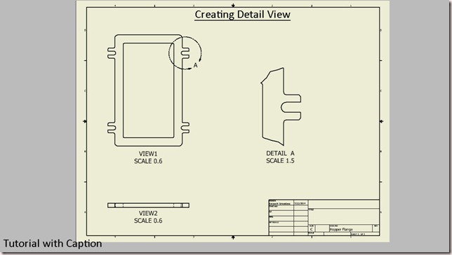
Creating Detail View

Video Tutorial with caption

download-Link


Click the following link to get the model file: - http://bit.ly/2Ch3zvc


Transcription of Video

  1. Open the Hopper Flange (.ipt) part file.
  2. Create a new Drawing sheet with metric template.
  3. Activate the Base View command from the marking menu.
  4. Notice that when the part file is already opened, here model file is automatically displayed in the File drop-down.
  5. View Orientation of the Base View should be (Top) and set the view scale to (0.6).
  6. Click the left mouse button at the upper side of the sheet. Then move your cursor downward of the base view followed by clicking the left mouse button.
  7. Click Create button from the context menu to generate the views.
  8. Save the file with the name Hopper Flange.
  9. Activate the ‘Detail View’ tool from the Create Panel and select the View1 to define it as the parent view.
  10. Detail View dialog box is visible in the graphics window.
  11. In the ‘Fence Shape’ field, there are two option first Circular and the second Rectangular for the detail view.
  12. The Circular shape is selected by default.
  13. Set View Scale 1.5 and click inside of this slot to define the center point of the fence.
  14. Drag the fence as displayed and click the right side of the sheet to place the detail view.
Creating a Section View (Autodesk Inventor 2013)

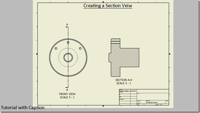
Creating a Section View

This tutorial displays how to create a Section View in the Drawing Sheet.

download-Link


Click the following link to get the model file: - http://bit.ly/2JT9ICc


Transcription of Video

  1. Create a new Drawing sheet with metric template.
  2. Activate the Base View command from the marking menu.
  3. Open the Housing Fixture (.ipt) part file.
  4. Set the View Scale of the base view 3:1 from the drop down list.
  5. Click the toggle visibility button.
  6. Enter the text FRONT VIEW in the ‘View Identifier’ field.
  7. Click OK to place the view.
  8. Save the drawing sheet with the name Housing Fixture.
  9. Activate Section View from the Create Panel and select the Base View to define it as the parent view.
  10. Hover the mouse pointer over parent view to find the dotted inference line which defines the Center of the Base View and click to start creating section line.
  11. Click Continue button from the right click context menu, Section View dialogue box appears. From here View identifier name and scale can be edited.
  12. Click in the design window to place the section view.
  13. Save the file.

Creating Base View and Projected View (Autodesk Inventor 2013)

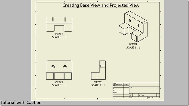
Creating Base View and Projected View in Drawing Sheet

This video tutorial displays how to create Base View and the Projected View along with View name and Scale label in a Drawing Sheet.


download-Link


  Click the following link to get the model file: - http://bit.ly/2JUuyRL 


Transcription of Video

  1. Here a blank drawing sheet is open, using the ANSI (mm).idw template.
  2. Right click in the graphics window and activate the ‘Base View’ command.
  3. Drawing View dialog box is visible in the design window.
  4. Click the ‘Open an existing file’ icon.
  5. Open the Mount Bracket.ipt file.
  6. In the Orientation field, there are different types of pre-defined view orientations that can be placed in the drawing page.
  7. Front view is selected by default.
  8. By default the view scale is 1:1 of the model which can be changed from here.
  9. If you hover the mouse over the drawing sheet, a preview of the Mount Bracket will be visible with the front view in the design window.
  10. Click the left mouse button at the bottom of the page. Then move your cursor upward and left side from the base view followed by clicking the left mouse button.
  11. At last, move the cursor on the upper right corner of the design window for placing the isometric view.
  12. Right click in the graphics window and click Create button in the context menu to generate the desired views.
  13. Save the drawing sheet with the name Mount Bracket.
  14. Double click the Base view to edit it.
  15. Click the ‘Toggle Label Visibility’ icon to show the View name and Scale label on the drawing sheet.
  16. Click OK to close the dialog box.
  17. In the same way edit the three other projected views.

Starting a New Drawing Sheet (Autodesk Inventor 2013)

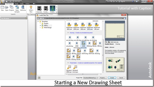
Starting a New Drawing Sheet

Video Tutorial with caption


Transcription of Video

  1. On the Quick Access toolbar, click the New icon.
  2. In the Create New File dialogue box, there are two types of pre-defined templates, one is English (inch) and the other is Metric (mm), from where Part, Assembly, Drawing and Presentation file can be created.
  3. In the Metric template, select the ANSI (mm).idw file.
  4. Click Create button to open the new drawing sheet.
  5. New Drawing sheet will be opened in the design window.

Modifying the Project file (Autodesk Inventor 2013)

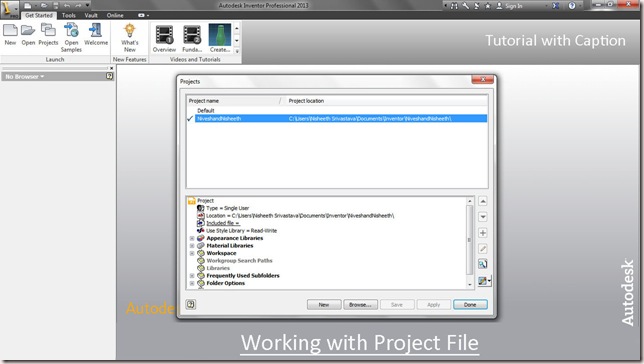
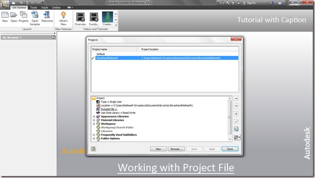
Working with Project File (Autodesk Inventor)

Video Tutorial with caption

In this video, we will describe modifying Style Library options, add shortcut paths to folders that you frequently access and set the location of Content Centre files save location in a specific project.


Transcription of Video

  1. In the top window of the Projects dialog box, double-click the NiveshandNisheeth project file to activate it.
  2. In the bottom window, right-click on the 'Use Style Library’ option.
  3. Here are two options, Read-Only/Read-Write. If you want to be able to edit style library and add new style library/local styles in this project, you can choose Read-Write option. If you don’t want, you can choose Read-Only option.
  4. Read-Only option is selected by default.
  5. Select Read-Write option in the context menu.
  6. Click the ‘Frequently Used Subfolders’ icon to highlight the row.
  7. On the right, click the Add New Path icon.
  8. A new row will be added under the row.
  9. In the field on the left, type Assemblies.
  10. On the right, browse to set your path as displayed.
  11. Click OK to set the path for the shortcut to the assembly files.
  12. In the same manner, create another shortcut for part files.
  13. Expand the Folder Options section.
  14. Click the Content Center Files icon, and click the Edit icon on the right.
  15. To add path for content center files, where we have previously created Project file.
  16. Click Save button to save the settings.
  17. Click Done button to close the dialogue box.
  18. In the left pane of the Open dialogue box Assemblies, Parts and Content centre files have been stored in each folder.

Working with Project Files (Autodesk Inventor 2013)

Working with Project File (Autodesk Inventor)

Video Tutorial with caption

A project file is a text file in .xml format with an .ipj extension. It tells Inventor where to look for component files when working with assemblies and drawings. You can have as many as projects needed to manage your work.

The project shortcut is located in the projects folder. The project file (.ipj) location is specified in the Project wizard when the project is created.


Transcription of Video

  1. Make sure that all files are closed in Inventor but Inventor software is still running.
  2. Go on the Ribbon > Launch panel and activate the Projects command.
  3. Projects dialogue box is displayed in front of you.
  4. Click the New button at the bottom of the dialogue box.
  5. Inventor project wizard dialogue box is displayed on the screen.
  6. Click the New Single User Project option, and then click the Next button at the bottom of the dialogue box.
  7. Enter the text in the Name field.
  8. Project (Workspace) Folder shows that where the project have been saved in your hard drive.
  9. The Project file of location can be changed manually from this ‘Browse for project location’ button.
  10. Click Finish button to create new project file.
  11. Now the Project file is created that you specified.
  12. Click Done button to close the dialogue box.

Friday, July 11, 2014

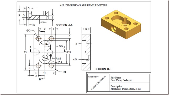
Gear Pump Body || Practice Exercise Drawing Sheet by Creo Parametric 2.0

Gear Pump Body-2

Create 3D Parametric Model with the help of given 2D Drawing Sheet.
This Practice lesson or Project is useful for Creo Parametric or any 3D Cad package.


download-Link


Get the drawing sheet as PDF by visiting the following link:-

http://bit.ly/2nRNQit

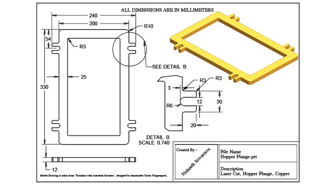
Hopper Flange || Practice Exercise Drawing Sheet by Creo Parametric 2.0

Hopper Flange-2

Create 3D Parametric Model with the help of given 2D Drawing Sheet.
This Practice lesson or Project is useful for Creo Parametric or any 3D Cad package.


download-Link


Get the drawing sheet as PDF by visiting the following link:-

http://bit.ly/2n4F1BJ

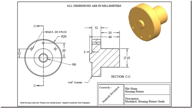
Housing Fixture || Practice Exercise Drawing Sheet by Creo Parametric 2.0

Housing Fixture-2

Create 3D Parametric Model with the help of given 2D Drawing Sheet.
This Practice lesson or Project is useful for Creo Parametric or any 3D Cad package.


download-Link 

Get the drawing sheet as PDF by visiting the following link:-

http://bit.ly/2mnObck

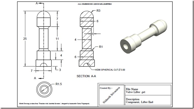
Valve Lifter || Practice Exercise Drawing Sheet by Creo Parametric 2.0

Valve Lifter-2

Create 3D Parametric Model with the help of given 2D Drawing Sheet.
This Practice lesson or Project is useful for Creo Parametric or any 3D Cad package.


download-Link


Get the drawing sheet as PDF by visiting the following link:-

http://bit.ly/2otJjCW

Wednesday, July 9, 2014

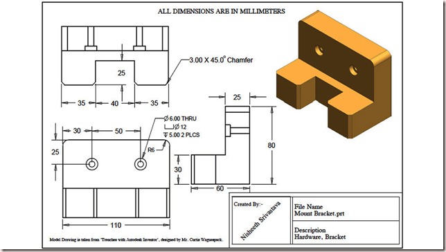
Mount Bracket || Practice Exercise Drawing Sheet by Creo Parametric 2.0

2 (1280x720)

Create 3D Parametric Model with the help of given 2D Drawing Sheet.
This Practice lesson or Project is useful for Creo Parametric or any 3D Cad package.


download-Link


Get the drawing sheet as PDF by visiting the following link:-

http://bit.ly/2mkqEsM

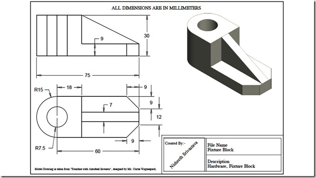
Fixture Block || Practice Exercise Drawing Sheet by Creo Parametric 2.0

2 (1280x720)

Create 3D Parametric Model with the help of given 2D Drawing Sheet.
This Practice lesson or Project is useful for Creo Parametric or any 3D Cad package.


download-Link


Get the drawing sheet as PDF by visiting the following link:-

http://bit.ly/2m7jE2j