Serial No. 23-A.
Drill Machine (Volume-1)—Solid Edge ST9 Tutorial
(Rest of the design of the model is completed in Volume-2)
In this Solid Edge Tutorial we will describe how to build the model ‘Drill Machine’. It is a Part and Assembly modelling tutorial. This assembly consist 1 Assembly and 22 part files (Drill Machine frame (Multi Body part) Spindle, Drill chuck, Gear, Pinion, Gear hub, Washer, Handle etc.) that are positioned according to design intent by using Assembly Constraints. This tutorial will give you a good practice of applying constraints in an assembly and give you an idea of Drill Machine mechanism.
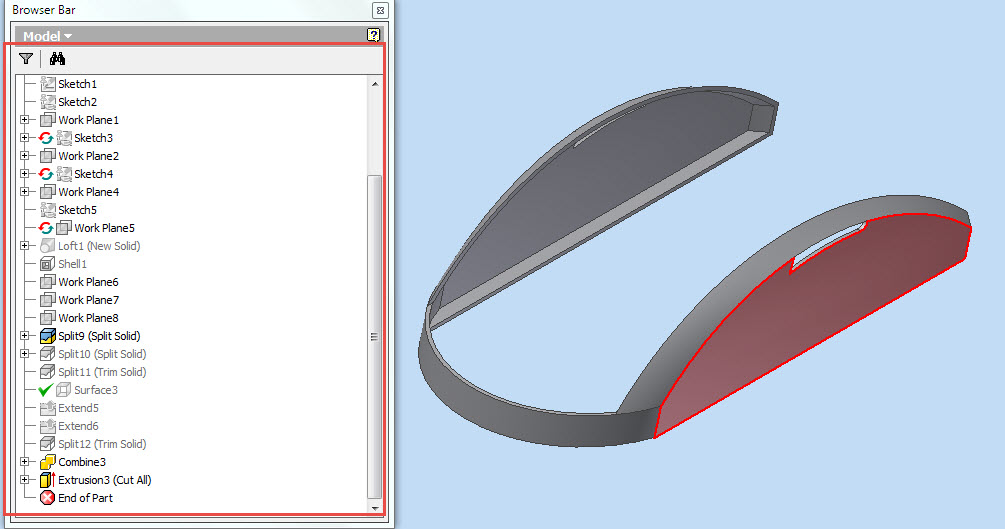
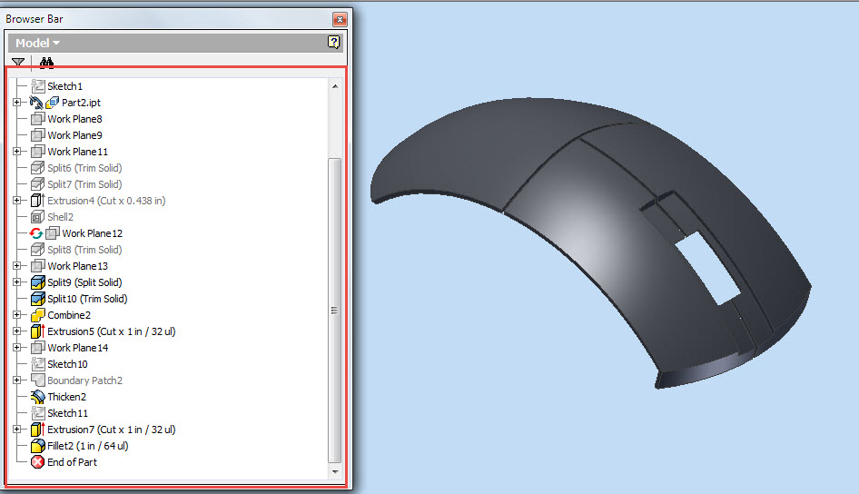
How to construct the part ‘Drill Machine Frame’ (Multi body part). After creating the frame convert all multi body parts into a single solid body with the help of ‘Union’ command.
It will cover the following topics.
........................................................................................................
• Creating 2D Sketches on different Planes.
• Use the sketch constraints that are applied on during sketch creation.
• Use features command such as Revolved, Extrude, Cut, Subtract, Intersection, Union, Add Body, Normal Cutout, Helical Cutout etc.
• Use the ‘Add Body’ command to create multiple bodies in a single part file (‘Drill Machine Frame’).
• Use the ‘Revolve’ command with different options.
• How to create a realistic thread in our model Spindle and Part1 (UNF Screw External &Internal Thread Profile) by sweeping a cross section along a helical path by using ‘Helical Cutout’ command.
• How to apply knurl image on the face of the model with the help of ‘Styles’ tool.
• How to change the color of the model by using ‘Part Painter’ tool.
• Use assembly commands such as Flash Fit, Axial Align mate, Connect mate, Mate/Planar Align command etc.
• How to mate the parts by using ‘Flash Fit’ command in the assembly.
• How to mating between the vertex point of gear and pinion by using ‘Connect Mate’ command.
• How to create gear relationship between gear and pinion by using ‘Gear’ mate command and how to define the number of teeth of the gear and pinion (15/56) to define the gear interaction.
• How to lock the rotation of the component by using ‘Lock Rotation’ option in ‘Flash Fit’ command in the assembly.
• How to flip the component by using ‘Flip Side’ option in ‘Flash Fit’ command in the assembly.
• How to rotate and moving part by using ‘Drag Component’ command.
• How to insert component into the assembly using drag and drop from parts library by using ‘Insert Component’ command.
• Use ‘Show/Hide Component’ option in the assembly to mate the components more easily.
• How to hide all components except the selected components by using ‘Isolate’ command in the assembly.

Click the following link to get the model file: - http://bit.ly/2LWL8BP