Showing posts with label 'Autodesk. Show all posts

Monday, November 18, 2013

Creating wires in Mesh of Table Fan-Autodesk Inventor 2013 (with caption and audio narration)


Creating wires in Mesh of Table Fan

Serial No.149

Creating wires in Mesh of Table Fan-Autodesk Inventor 2013 (with caption and audio narration)
.......................................................................
This video will display how to create wires of the mesh of our previously created model 'Mesh of Table Fan'.


download-Link 


Click the following link to get the drawing sheet of the model: - http://bit.ly/2neUSNX


 Transcription of Video

Creating wires in Mesh of Table Fan

This video will display how to create wires of mesh of our previously created model ‘Mesh of Table Fan’.

  1. At present there are three components Part1, Part2 and Part3 in the Assembly.
  2. And we want to create 3 more new components Part4, Part5 and Part6 like this.
  3. We will start our work with creating a new component in the Assembly.
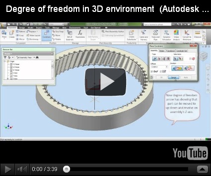
  4. At present the newly created component is not fully constrained in the Assembly, which can be confirmed by checking the ‘Degrees of Freedom’.
  5. To fully constrain it in the Assembly, we will apply Mate Constraint between Center Point of Part4 and Center Point of Assembly.
  6. Next, we will apply a Mate Constraint between Z Axis of Part4 and Z Axis of Assembly.
  7. And finally a Mate Constraint between XZ Plane of Assembly and XZ Plane of Part4.
  8. Now the Part is fully constrained, there are no Degrees of Freedom left.
  9. In this Assembly, a ‘Component Pattern’ feature was applied to replicate the Part3.
  10. We will ‘Suppress’ this feature and make visible only one instance of the Part3.
  11. By double clicking the Part4, we will now enter in the Part Modelling environment.
  12. Our first sketch will be drawn on the XZ Plane of Part4.
  13. First we will project the edges of the other components available in the Assembly, using the ‘Project Cut Edges’ Command.
  14. We will use these edges as a reference for creating new sketch. That is why we will apply a construction override on these projected edges. This will prevent them from being recognized as profiles by the 3D features.
  15. This offset length is equal to the radius of wire of mesh.
  16. Now we are applying constraints on our sketches to position it properly. This will also make our sketch Fully Constrained.
  17. We will create a Work Point on this newly created sketch and replicate it 22 times with the use of ‘Rectangular Pattern’ Tool.
  18. Select ‘Curve Length’ to place the Work Points along the path of the sketch.
  19. Now start a new sketch on the XZ Plane of Part4.
  20. Now project this Work Point on the sketch with the use of ‘Project Geometry’ Tool.
  21. Draw a circle on this point.
  22. Now we will develop our first wire of mesh with the help of ‘Revolve feature’.
  23. Change the colour of Part4 to 'Steel'.
  24. Repeat the same steps to generate other wires of mesh.
  25. Clear the screen by activating the 'Clean Screen' Command.
  26. The fully developed Assembly will look like this.

Creating hole on a curve surface-Autodesk Inventor 2013 (with caption and audio narration)


Creating hole on a curve surface

Serial No.148

Creating hole on a curve surface-Autodesk Inventor 2013 (with caption and audio narration)
..................................................................................
In this Video, we will show how to create holes on a Curved Surface using our Model 'Strainer'.


   download-Link

Click the following link to get the drawing sheet of the model: http://bit.ly/2o5IwIj


Transcription of Video

Creating hole on a curve surface

In this Video we will show how to create holes on a Curved Surface using our Model ‘Strainer’.

  1. This is the model of ‘Strainer’ on which we want to create holes on it curved surface like this.
  2. First of all, we will enter in the part modelling environment by double clicking the Part1.
  3. We have already created Work Points on the curved surface of Strainer on the basis of a previously created sketch.
  4. These are all the Work Points, which you can see in the Browser Bar as well as in the design window.
  5. In the half section view, you can see it clearly that all the Work Points are landing on the curved face on the Strainer.
  6. This is the sketch on the basis of which all the Work Points were created earlier.
  7. A sketch of hole is required to create a hole on the Work Point.
  8. So first of all we will create a Work Plane on the Work Point that would be tangent to the curved surface of the Strainer.
  9. Take the project of Work Point and start the Circle Tool to create a circle of 0.03125 unit length.
  10. Finish the sketch.
  11. To create a hole on this sketch, we will use Extrude Command.
  12. Click Extrude from the Create Panel of 3D Model Tab.
  13. Click the circular profile.
  14. In the direction field, select ‘Symmetric’ option.
  15. Select ‘Cut’ option to remove the material from the curved surface of the Strainer and the hole is created.
  16. Turn off the visibility of the Work Plane.
  17. Now we will use the Circular Pattern Tool, that will replicate this extrude feature 80 times.
  18. First select the feature then the rotation axis.
  19. We will select the rotation axis as Y Axis from the Browser Bar.
  20. In the Placement field type 80.
  21. All the holes are now created.
  22. In the same way, we will create another hole on this Work Point.
  23. Same operations are being performed.
  24. This time we will activate the Extrude Command by just clicking the sketch, here you can see.
  25. The Extrude Command is visible there.
  26. In the second row, the circumference of the model has decreased, so we have to select less number of holes (i.e., 78 occurrences) in this Circular Pattern.
  27. In the same manner other holes can be created on the curved surface of the object easily, to get the desired result.
  28. Here is the finished Assembly of the Strainer you can see all the holes are here.

Creating a component in an assembly-Autodesk Inventor 2013 (with caption and audio narration)


Creating a component in an Assembly


Serial No. 147

Creating a component in an assembly-Autodesk Inventor 2013 (with caption and audio narration)

This video will display how to create a component in the context of an Assembly. Creating a component in this way has many benefits. We can Project faces and edges of the Assembly in the new component.  The faces of other components can be copied and placed on surfaces and many more things can be done. So watch the video to understand.


Transcription of Video

Creating a component in an Assembly

This video will display how to create a component in the context of an Assembly. Creating a component in this way has many benefits. We can Project faces and edges of the Assembly in the new component. The faces of other components can be copied and placed as surfaces and many more things can be done. So watch the video to understand.

  1. We have an Assembly named ‘Mesh (Front)’ consisting two components ‘Part1’ and ‘Part2’.
  2. Now we want to create a new component named ‘Part3’ in this Assembly like this.
  3. The Vertical distance between Part1 and Part2 is 1.625 inch.
  4. We will start our work with creating a new component in this Assembly.
  5. The degree of freedom command shows that the newly created Part3 is not fully constrained with the Assembly.
  6. So we will apply a Mate Constraint between the Part3 and Assembly’s Z Axis.
  7. Next a Mate Constraint will be applied between XZ Planes of Assembly and Part3.
  8. In the following steps, we will create a loft feature in this component with the help of two sketches and a centre line rail.
  9. By double clicking the Part3 we will enter in the Part Modelling Environment.
  10. First of all we will get the edges of previously created components with the use of ‘Project Geometry Tool.’
  11. These projected geometries are required only for reference. We are actually going to use these geometries in the developing the loft feature, that is why we will convert them in Construction Geometry.
  12. By applying Coincident Constraint we will properly position our geometry.
  13. Again unnecessary sketches will be converted into Construction Geometry.
  14. So we have created the required sketch now.
  15. Now we will create a New Work Plane parallel to YZ Plane of Part3 (7.625 inch away).
  16. Now we will create the remaining sketch on the XZ Plane of the Part3 that will be used for Centre line loft.
  17. From here we will change the colour of the Part to ‘Being Personal.’
  18. In the next following steps we will develop the second loft feature in this Part.
  19. At present we are copying the outer face of the Part2 with the ‘Copy Object’ Tool. This will place a new surface component in this part.
  20. Now we will project this sketch on the previously created surface component with the help of ‘Project to 3D Sketch’ Tool.
  21. At present this 3D sketch is intact. We cannot use its one edge as a rail in the loft feature. So we will create a new 3D sketch and project its one edge in it with the use of ‘Include Geometry’ Tool.
  22. Repeat the same process to create the second Rail.
  23. In this way, we found our two separate rails required for the loft.
  24. Now we will create two 3D sketch profiles required for the loft.
  25. So everything is set. Start the ‘Loft’ Tool.
  26. Model edges can also be used as rails.
  27. So in this way we created our second loft feature in the Part3.
  28. We will now replicate this (Part3) 8 times at an angle of 45 degree by using ‘Pattern Component’ Tool, available at Component Panel of Assembly Tab.
  29. If you want to watch the development of other components, used in the ‘Mesh of Table Fan’ Assembly, watch our previous video named ‘Mesh of Table Fan’ (Autodesk Inventor 2010).

Rotate and Place components in an Assembly-Autodesk Inventor 2013 (with caption and audio narration)


Rotate and Place components in an Assembly


Serial No. 146

Rotate and Place components in an Assembly-Autodesk Inventor 2013 (with caption and audio narration)

In this Video we will describe about rotating and placing components in an Assembly.


Transcription of Video

Rotate and Place components in an Assembly

In this Video we will describe about rotating and placing components in an Assembly.

  1. We have following components, which we want to place and constrain in an Assembly like this.
  2. So create a New Assembly File and start placing the components.
  3. The first component placed in an Assembly is always ‘Grounded’ and there is no need to constrain it.
  4. Now we are going to place the ‘Part8’ in the Assembly.
  5. To properly position the Part8 for Mate we will use ‘Rotate Component’ Command which is located in the Position Panel of Assemble Tab.
  6. After selecting the Part8, click anywhere outside the reticle to start the rotation.
  7. The component is positioned for the Mate now.
  8. Start the ‘Constrain’ Tool.
  9. Click this face and then this face.
  10. Now click Apply.
  11. The Rewind Tool is very useful to restore the most recent view or scroll through all of the save views.
  12. In the same way, other four Parts can be placed, positioned and constrained to get the desired result…..
  13. Now Assembly is fully constrained, there are no Degrees of Freedom that can be checked in this way…

Application of 3D sketch with loft feature-Autodesk Inventor 2012 (with caption and audio narration)

Application of 3D sketch with loft feature 

Serial No. 145

Application of 3D sketch with loft feature-Autodesk Inventor 2012 (with caption and audio narration)

In this video, we will describe 3D sketch and its application in the creation of loft feature.


download-Link

Click the following link to get the drawing sheet of the model: http://bit.ly/2m51dLC


 Transcription of Video

Application of 3D sketch with loft feature

In this video we will describe about 3D sketch and its application in creation of loft feature.

  1. This is our sketch which is named Sketch5 in the browser.
  2. It is 2 inch up vertically from this point.
  3. This sketch is placed on the Work Plane5.
  4. Work Plane5 is 4.5 inch away from the Work Plane4.
  5. Now we want to connect Sketch5 to the cup of the Spoon like this.
  6. For this we will create two 3D sketches.
  7. Start a 3D sketch from the Sketch panel of the Model Tab.
  8. Create 3D line and close the sketch like this.
  9. Once again create another 3D sketch in the same manner.
  10. So the required two 3D sketches are in hand which we will use for developing the handle of Spoon.
  11. Now pick up the loft tool from the Create panel of the Model Tab and develop the handle of Spoon like this.

Application of browser bar in Autodesk Inventor (with caption and audio narration)


Application of browser bar in Autodesk Inventor


Serial No. 144 

Application of browser bar in Autodesk Inventor (with caption and audio narration)

In this video, we will tell you about the Browser Bar of Autodesk Inventor Software and its use.
Autodesk Inventor is referred to as parametric solid modelling software. It maintains the history of how parts were constructed. The history will also show how they are related to one another in an Assembly. You can monitor this by observing the Browser Bar.


Transcription of Video

Application of Browser Bar in Autodesk Inventor

In this video we will tell you about the Browser Bar of Autodesk Inventor Software and its use.

Autodesk Inventor is referred to as parametric solid modelling software. It maintains the history of how parts were constructed. The history will also show how they are related to one another in an Assembly. You can monitor this by observing the Browser Bar.

Browser in Part Modelling Environment

How to observe history of parts.

  1. Currently we are opening the model of Anvil.
  2. This is the Browser Bar.
  3. From here you can check, what the designing process of this CAD Model was.

Browser in Assembly Modelling Environment

How to observe relation of Parts in the Assembly

  1. Currently we are opening the model of Shaving Razor.
  2. In the case of Assembly you can understand the history of modelling as well as relation of parts to one another by exploring the Mate Constraints.

Application of Split Tool-Autodesk Inventor 2012 (with caption and audio narration)


Application of Split tool


Serial No. 143

Application of Split Tool-Autodesk Inventor 2012 (with caption and audio narration)
In this Video, we will describe 'Split' Tool and its application in cutting a segment from an intact face.


download-Link 


Click the following link to get the drawing sheet of the model: http://bit.ly/2m51dLC


Transcription of Video

Application of Split tool

In this Video we will describe about ‘Split’ Tool and its application in cutting a segment from an intact face.

  1. At present this face of the Spoon is intact. We need a segment of this face according to our design like this.
  2. To do so, first we will create a Work Plane on the top edge of the Spoon.
  3. Now we will create a line of 0.25 inch on this Work Plane.
  4. We will use the ends of this line to create new Work Planes later.
  5. These newly created Work Planes will be used as Splitting Tool.
  6. Now start the ‘Split’ Tool.
  7. Select ‘Split Face’ option in the Split tool dialog box.
  8. Select the Work Plane for the splitting tool.
  9. Use the Select face button for faces.
  10. Select the intact face of the Spoon and click Apply.
  11. Repeat the same process for next split.
  12. So this is the segment of face which was split.
  13. We can change the colour of this face to yellow. So that it can be recognized easily.

Saturday, March 30, 2013

Using equations in Autodesk Inventor

If you want to use equations in the Autodesk Inventor then first write it down in Microsoft Office using insert equation tool. Then change the equation option to linear. Now make changes according to following link (valid formula syntax and abbreviations can be used in Autodesk Inventor). Now you can use your equations without any error.
Take a look on the following page too to get an overall knowledge how equations are written in Autoedsk Inventor. Formulas for "Everyday" Use.

Deck (Architectural Model) Autodesk Inventor 2012


Here are some more images of Deck after some modification using visual styles.  After visiting the view tab> appearance panel  you will find lightning styles. Image-based lights styles are very useful for the visualization of you model. Image-based lights, also called IBL, derive their lighting parameters from high dynamic range (HDR) images. The image provides a source location and luminance or radiance values that correspond more with real world lighting, providing a more realistic viewing experience.
Deck (Architectural Model) Autodesk Inventor 2012
Above picture was before applying the Visual Stiles and the following images are after applying the visual styles:--
Assembly1 Assembly2 
There are many setting that can be done after applying predefined styles.

Monday, June 18, 2012

STL files for CAD Users (3D Printing)


Watch the following video to understand how useful is .stl files for cad users. This file is used for 3D printing also

Visit the following link to see the actual experience.
http://grabcad.com/library/mesh-of-table-fan

Monday, May 28, 2012

Working with Autodesk Inventor (Faster)

If you want to run your Autodesk Inventor faster apply these settings. This tip is more useful for them who are running this software on an old desktop or laptop.

Thursday, May 17, 2012

Assembly Constraints and Degrees of Freedom (Autodesk Inventor)

The purpose of constraining components together in an assembly is to imitate (copy)  the behaviour of components in the real world. By giving constraints we remove degree of freedom of a part in the an assembly. Although it is not necessary to remove all degrees of freedom. We need as many as to properly position the part. See below how degrees of freedom works in sketch and assembly environment:-

First video

Second video

There is a new tool for degree of freedom Degree of Freedom Analysis to understand watch the following video.

Want to know more about this topic visit following link :-Degree of Freedom Analysis

Sunday, May 6, 2012

Hardware Splined Drill Bit (Video Tutorial) Autodesk Inventor 2012


I found the 2D drawing of this model from Mastering Autodesk Inventor book (Autodesk Inventor Practice Part Drawings) and converted it in a 3D model. To know more about the book visit the following link   http://bit.ly/sorjmlearningrp

To download the finished file visit the following link :-
http://www.mediafire.com/?rzzkyzu8mcxjd

For any further assistance on this topic, ask your questions at the following forum:-
http://forums.autodesk.com/t5/Autodesk-Inventor/bd-p/78

Friday, May 4, 2012

Setting Application Options and Creating a Template File in Autodesk Inverntor

There are many setting which allow us to customize the work environment in Autodesk Inventor.
In the following video I will show which Application Option setting we are using that is visible in our videos tutorials most of the time. People many a times ask us why your design window is different and what My Preference .ipt is. By applying the settings displayed in the video your design window will be the same as ours.

The current background setting of our design windows is different and we keep changing it according to our mood....:)

Thursday, April 26, 2012

Saturday, April 21, 2012

Find Command Location Autodesk Inventor 2012 (Transparency ON/OFF)


Command Location tool of Autodesk Inventor 2012.
This tool is used to search tool while working on Inventor.  It will be more useful when we  are not sure about the name of the tool we are looking for. Many a times when we forget where a tool is located then this utility can be used. By just typing the name it starts giving the hits just like Google/Windows search.

Thursday, May 12, 2011

Component Generators-Spur Gears (Autodesk Inventor 2012)


Component Generators-Spur Gears (Autodesk Inventor 2012)
With the help of Component Generators any type of gears can be created in Autodesk Inventor.
It is very useful feature of this software. Watch the video to know how it works.

Watch the following videos these are new addition:-


This video is inspired from the Skill Builders Examples available on the official web sight of Autodesk Inventor Software. To properly understand the Component Generator's Supur Gear function visit the following link:-
http://usa.autodesk.com/adsk/servlet/item?siteID=123112&id=10008317


This video is inspired from the Book Autodesk Inventor 2012 Essentials. Read the book to understand it more clearly.Visit the following link to know about the book:---
http://nisheeth-inventortalks.blogspot.in/p/other-learning-resources.html

This video is inspired from the Book Mastering Autodesk Inventor 2012. Read the book to understand it more clearly.Visit the following link to know about the book:---
http://nisheeth-inventortalks.blogspot.in/p/other-learning-resources.html

Saturday, April 16, 2011

Helical Gear (Internal)-Dynamic Simulation through Autodesk Inventor 2010


Following video will explain about Dynamic Simulation of Autodesk Inventor 2010. See how after giving the proper constraints, the gears can be Animated.

Helical-Gear-(Internal)-Dynamic-Simulation 
 

HD Link for this video

To download the finished file, visit the following link:-- http://www.mediafire.com/?32pc9d8s2iabvqk


Wednesday, December 22, 2010

Surfaces Feature -Autodesk Inventor Tutorial


Surfaces Feature -Autodesk Inventor Tutorial

In this video tutorial I will explain you how to model Tray. During this process you will learn Autodesk Inventor Surfaces features. We will create Surfaces with the help of 'Boundary Patch ' and Loft tools.
 Tray-View-1 Tray-View--2


HD Link for this video
To download the finished file, visit the following link:-- http://www.mediafire.com/?uh74cn5xpc9gg73