
Serial No. 247
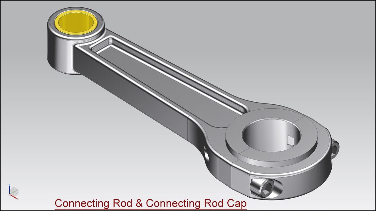
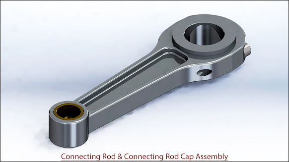
Connecting Rod and Connecting Rod Cap Assembly (SolidWorks 2017 Tutorial)
Hi Viewers, Today we will design two models 'Connecting Rod and Connecting Rod Cap' in SolidWorks 2017. In this video, you will learn the full modelling process of these models and afterwards, we will place components in the Assembly.
This Video will cover:
1. Create basic 2D sketches on different work planes like Front, Top and Right with the help of Line, Circle, and Rectangle tools.
2. Create a solid feature by using the Extrude Boss/Base, Extruded Cut, Revolve Boss/Base, Swept Cut, Fillet, Hole, Mirror Feature and Chamfer commands.
Hope all of you enjoyed the tutorial.

Click the following link to get the model file: - https://bit.ly/3vFShMs
....................................................................................
Visit the following link to watch the basic tutorial on SolidWorks by us
https://www.youtube.com/playlist?list=PLb-IhKRMYSES3Zw3QHmQVqQ-rcFVzgYHy
.........................................................................
To watch more detailed tutorials on the same software visit the following link
https://www.youtube.com/playlist?list=PLKWX3xUP3pPo77gFCyy669sI76qJa5jKw
...................................................................................
Hope all of you enjoyed the tutorial. If you find the video useful please like it and share it with your friends/colleagues and do not forget to subscribe us to get latest updates about our new uploads.
http://www.youtube.com/user/nisheethsorjm?sub_confirmation=1
....................................................................................................
Dear Viewers if you like our work and wanted to support us, to keep continuing the good work, then become a patron of ours at ‘Patreon’ site. Patreon is a simple way for you to contribute to the creator’s work every month/ every time they release their new work and get rewards in return. Please visit the following link to know all about our work and what we are offering a reward to our patrons…
https://www.patreon.com/nisheethsri
...................................................................................................................................