Showing posts with label Inventor 2018 Tutorial. Show all posts

Saturday, September 2, 2023

Car Engine (2Turbo V6) Advanced Assembly Designing--Volume_2 (Autodesk Inventor 2018 Tutorial)

Car 2-Turbo V6 Engine Asembly Designing_2

Car 2-Turbo V6 Engine Asembly Designing_3


Serial No. 347-B.

Dear Viewers, Today we will design the 'Car Engine (2 Turbo V6) Advanced Assembly Designing' in the Autodesk Inventor 2018 version. In the second part of this assembly video, I will show you how to make 12 remaining parts and 1 Main Assembly to complete this tutorial. If you want to see the initial components of this assembly being made, then you can watch my first part of the video by going to this link.

So please click here on this link to watch it......... https://youtu.be/FuL9qkt2kGc

.......................................................................................................................

This Assembly tutorial covers topics from Inventor Basics like 2-D sketching and Part/Assembly modelling. This assembly contains several parts such as the Engine Valve, Rocker Spring, Belt Wheel, Intake Manifold, Engine front Cover, Engine Oil Pan, Air Turbo, Engine Valve Cover, Hose Pipe etc., and One main Assembly. First, we create the Engine Valve part then later each component is created individually with no relation to each other which you can term the Bottom-up designing process. In this process, the 12 parts are designed individually, and afterwards, all parts and subassemblies are inserted into the main assembly by using the assembly constraints. When the parts have been modified the changes also appear in the assembly.

This Video will cover:-

1. Create basic 2D sketches on different datum planes like XY, YZ and XZ with the help of Lines, Circles, Rectangles, 3-point arcs, 3D sketching, 3D sketch lines, 3D Spline etc.

2. Create a solid feature by using the Extrude, Extruded with the cut option, Revolve, Revolve with the cut option, Create a Shekk feature, Loft tool, Complex Loft feature with Rails/Centre Line Rails, Hole tool, Fillet, Mirror Feature, Rotate/Move Feature, Combine, Pattern/Mirror Feature and Chamfer commands.

3. Surface features like extrude with surface option, Lofted Surface, Extend Surface, Trim Surface, Offset surface, Stitch surfaces etc.

4. Place the part in the Assembly by using the Place Components command.

5. Use the 'Mate' command to position two components relative to one another by using such as Mate/Flush, Insert mate, and Angle mate with the Directed angle option.

6. Apply the Transitional mate between Cam and Follower in an assembly.

7. Apply the Gear Mate between Cam and Follower in an assembly.

Hope all of you enjoyed the tutorial.


Click the following link to get the model file: - https://bit.ly/45Sb6fN


....................................................................................................
Visit the following link to watch the basic tutorial on Autodesk Inventor by us
https://www.youtube.com/playlist?list=PLb-IhKRMYSERYpB48aY-sZ10fN6CfXIL4
.........................................................................
To watch detailed tutorials on the same software visit the following link
https://www.youtube.com/playlist?list=PL74BDF7431ED13443
..........................................................................................
Hope all of you enjoyed the tutorial. If you find the video useful please like it and share it with your friends/colleagues and do not forget to subscribe us to get latest updates about our new uploads.
http://www.youtube.com/user/niveshandnisheeth?sub_confirmation=1
....................................................................................................
Dear Viewers if you like our work and wanted to support us, to keep continuing the good work, then become a patron of ours at ‘Patreon’ site. Patreon is a simple way for you to contribute to the creator’s work every month/ every time they release their new work and get rewards in return. Please visit the following link to know all about our work and what we are offering as the reward to our patrons…
https://www.patreon.com/nisheethsri+

Car Engine (2Turbo V6) Advanced Assembly Designing -- Volume_1 (Autodesk Inventor 2018 Tutorial)


Car 2-Turbo V6 Engine Asembly Designing_1


Car 2-Turbo V6 Engine Asembly Designing_4


Serial No. 347-A.

Dear Viewers, Today we will design the 'Car Engine (2 Turbo V6) Advanced Assembly Designing' in the Autodesk Inventor 2018 version. In the first part of this assembly video, I will show you how to make 15 parts and a subassembly. I will do the remaining components and the main assembly complete in the second part of this video. If you want to see the remaining components of this assembly being made, then you can watch my second part of the video by going to this link.

So please click here on this link to watch it......... https://youtu.be/izaypoAdDrY

.......................................................................................................................

This Assembly tutorial covers topics from Inventor Basics like 2-D sketching and Part/Assembly modelling. This assembly contains several parts such as Piston Rod, Piston Rod Cap, Piston Head, Crank Shaft, Engine Block, Engine Cylinder Head, Air Filter etc., and One mini subassembly named Rocker Arm. First, we create the Piston Rod part then later each component is created individually with no relation to each other which you can term the Bottom-up designing process. In this process, the parts are designed individually, and afterwards, all parts and subassemblies are inserted into the main assembly by using the assembly constraints. When the parts have been modified the changes also appear in the assembly. This Video will cover:-

1. Create basic 2D sketches on different datum planes like XY, YZ and XZ with the help of Line, Circle, Rectangle, 3 Point Arc, etc.

2. Create a solid feature by using the Extrude, Extruded with cut option, Revolve, Revolve with cut option, Loft tool, Loft tool with Cut operation, Hole tool, Fillet, Mirror Feature, Rotate/Move Feature, Combine, Pattern/Mirror Feature and Chamfer commands.

Hope all of you enjoyed the tutorial.


Click the following link to get the model file: - https://bit.ly/45Sb6fN


....................................................................................................
Visit the following link to watch the basic tutorial on Autodesk Inventor by us
https://www.youtube.com/playlist?list=PLb-IhKRMYSERYpB48aY-sZ10fN6CfXIL4
.........................................................................
To watch detailed tutorials on the same software visit the following link
https://www.youtube.com/playlist?list=PL74BDF7431ED13443
..........................................................................................
Hope all of you enjoyed the tutorial. If you find the video useful please like it and share it with your friends/colleagues and do not forget to subscribe us to get latest updates about our new uploads.
http://www.youtube.com/user/niveshandnisheeth?sub_confirmation=1
....................................................................................................
Dear Viewers if you like our work and wanted to support us, to keep continuing the good work, then become a patron of ours at ‘Patreon’ site. Patreon is a simple way for you to contribute to the creator’s work every month/ every time they release their new work and get rewards in return. Please visit the following link to know all about our work and what we are offering as the reward to our patrons…
https://www.patreon.com/nisheethsri+

Thursday, July 13, 2023

Roots Blower Assembly (Autodesk Inventor 2018 Tutorial)


Roots Blower_1

Roots Blower_3

Roots Blower_2


Serial No. 345.

Dear Viewers, Today we will design the 'Roots Blower Assembly' in Autodesk Inventor 2018 version. This Assembly tutorial covers topics from Inventor Basics like 2-D sketching and Part/Assembly modelling. This assembly contains 4 parts Housing, Cover, Shaft, Impellers & Two Spur Gears, and One Assembly. Mainly the Spur Gears are generated by the “Spur Gear generator” command under the Design Accelerator tab in Inventor. First, we create the Housing part then later each component is made individually with no relation to each other which you can term the Bottom-up designing process. In this process, the four parts are designed individually, and afterwards, all parts are inserted into the main assembly by using the assembly constraints. When the parts have been modified the changes also appear in the assembly.

This Video will cover:-

1. Create basic 2D sketches on different datum planes like XY, YZ and XZ with the help of a Centre Point Slot, Line, Circle, Rectangle, 3 Point Arc, etc.

2. Rectangular sketch Pattern with curve length option this is the main section of this you will learn this.

3. Create a solid feature using the Extrude, Extruded with the cut option, Rectangular Pattern, Circular Pattern & Mirror Feature commands.

4. How to place the components in an Assembly by using the Place Components command.

5. Use the 'Mate' command to position two components relative to one another by using such as Mate/Flush, Motion, Rotation/Translation mate, and Angle mate with the Directed angle option.

6.. How to apply the Motion constraint between the two Impellers, especially for rotation of the Gears.

  7. How to insert the Spur Gears by the “Spur Gear generator” command under the Design Accelerator tab in Inventor.

8. . How to insert the bolts by using Autodesk Inventor Content Center Library files.

9. After completing this video we will display the animation of this model by using the Drive Constrain command.

Hope all of you enjoyed the tutorial.


Click the following link to get the model file: - https://bit.ly/3XPdPDU


....................................................................................................
Visit the following link to watch the basic tutorial on Autodesk Inventor by us
https://www.youtube.com/playlist?list=PLb-IhKRMYSERYpB48aY-sZ10fN6CfXIL4
.........................................................................
To watch detailed tutorials on the same software visit the following link
https://www.youtube.com/playlist?list=PL74BDF7431ED13443
..........................................................................................
Hope all of you enjoyed the tutorial. If you find the video useful please like it and share it with your friends/colleagues and do not forget to subscribe us to get latest updates about our new uploads.
http://www.youtube.com/user/niveshandnisheeth?sub_confirmation=1
....................................................................................................
Dear Viewers if you like our work and wanted to support us, to keep continuing the good work, then become a patron of ours at ‘Patreon’ site. Patreon is a simple way for you to contribute to the creator’s work every month/ every time they release their new work and get rewards in return. Please visit the following link to know all about our work and what we are offering as the reward to our patrons…
https://www.patreon.com/nisheethsri+

Tuesday, February 14, 2023

Pneumatic Motor Assembly (Autodesk Inventor 2018 Tutorial)


Pneumatic Motor Assembly_1


Pneumatic Motor Assembly_2


Serial No. 337.

Pneumatic Motor Assembly (Autodesk Inventor 2018 Tutorial)

Dear Viewers, Today we will design the 'Pneumatic Motor Assembly' in Autodesk Inventor 2018 version. This Assembly tutorial covers topics from Inventor Basics like 2-D sketching, Part/Assembly modelling. This assembly contains 12 parts Crankshaft, Connecting Rod, Piston,Cylinder Head, Motor Block, Mounting Bracket etc., and One Assembly. First, we create the Base Plate part then later each component is created individually with no relation to each other which you can term the Bottom-up designing process.

In this process, the twelve parts are designed individually, and afterwards the entire parts are inserted into the main assembly by using the assembly constraints. When the parts have been modified the changes also appear in the assembly.

This Video will cover:-

1. Create basic 2D sketches on different datum planes like XY, YZ and XZ with the help of Line, Circles, Rectangles, 3 Point Arc, etc.

2. Create a solid feature by using the Extrude, Extruded with cut option, Revolve, Hole tool, Fillet, Mirror Feature, Mirror Feature and Chamfer commands.

3. Place the part in Assembly by using the Place Components command.

4. Use the 'Mate' command to position two components relative to one another by using such as Mate/Flush, Insert mate, and Angle mate with the directed/undirected option.

5. Bolts are also placed in the Autodesk Inventor Content centre libraries.

6. After completing this video we will display the animation of this model by using the Drive Constrain command.

Hope all of you enjoyed the tutorial.


Click the following link to get the model file: - bit.ly/3E5nOwc


....................................................................................................
Visit the following link to watch the basic tutorial on Autodesk Inventor by us
https://www.youtube.com/playlist?list=PLb-IhKRMYSERYpB48aY-sZ10fN6CfXIL4
.........................................................................
To watch detailed tutorials on the same software visit the following link
https://www.youtube.com/playlist?list=PL74BDF7431ED13443
..........................................................................................
Hope all of you enjoyed the tutorial. If you find the video useful please like it and share it with your friends/colleagues and do not forget to subscribe us to get latest updates about our new uploads.
http://www.youtube.com/user/niveshandnisheeth?sub_confirmation=1
....................................................................................................
Dear Viewers if you like our work and wanted to support us, to keep continuing the good work, then become a patron of ours at ‘Patreon’ site. Patreon is a simple way for you to contribute to the creator’s work every month/ every time they release their new work and get rewards in return. Please visit the following link to know all about our work and what we are offering as the reward to our patrons…
https://www.patreon.com/nisheethsri+

Friday, September 9, 2022

Metallic Frame fitted along the Edges of Acrylic Sheet Autodesk Inventor 2018 Tutorial

Metallic Frame for Acrylic Plastic Sheet to Cover Edges

Serial No. 332

In this video, we create the first part Acrylic Sheet within the Assembly file and afterward, create two Side Frames by using the sheet metal command Contour Flange, after creating this we create a Flat pattern of the Side Frame in Autodesk Inventor 2018 Software.


Click the following link to get the model file: - https://bit.ly/3Rv7aehs


....................................................................................................
Visit the following link to watch the basic tutorial on Autodesk Inventor by us
https://www.youtube.com/playlist?list=PLb-IhKRMYSERYpB48aY-sZ10fN6CfXIL4
.........................................................................
To watch detailed tutorials on the same software visit the following link
https://www.youtube.com/playlist?list=PL74BDF7431ED13443
..........................................................................................
Hope all of you enjoyed the tutorial. If you find the video useful please like it and share it with your friends/colleagues and do not forget to subscribe us to get latest updates about our new uploads.
http://www.youtube.com/user/niveshandnisheeth?sub_confirmation=1
....................................................................................................
Dear Viewers if you like our work and wanted to support us, to keep continuing the good work, then become a patron of ours at ‘Patreon’ site. Patreon is a simple way for you to contribute to the creator’s work every month/ every time they release their new work and get rewards in return. Please visit the following link to know all about our work and what we are offering as the reward to our patrons…
https://www.patreon.com/nisheethsri+

Saturday, May 14, 2022

Four Cylinder Engine Assembly (Autodesk Inventor 2018 Tutorial)


Capture


Capture_1


Serial No. 329.

Four Cylinder Engine Assembly (Autodesk Inventor 2018 Tutorial)

Dear Viewers, Today we will design the 'Four-Cylinder Engine Assembly' in Autodesk Inventor 2018 version. This Assembly tutorial covers topics from Inventor Basics like 2-D sketching, Part/Assembly modelling. This assembly contains 6 parts Crankshaft, Connecting Rod, Piston, etc., Two SubAssemblies, and One Assembly. First, we create the Piston part then later each component is created individually with no relation to each other which you can term the Bottom-up designing process. In this process, the six parts are designed individually, and afterwards, all parts and subassemblies are inserted into the main assembly by using the assembly constraints. When the parts have been modified the changes also appear in the assembly.

This Video will cover:-

1. Create basic 2D sketches on different datum planes like XY, YZ and XZ with the help of Line, Circle, Rectangle, 3 Point Arc, etc.

2. Create a solid feature by using the Extrude, Extruded with cut option, Revolve, Revolve with cut option, Hole tool, Fillet, Mirror Feature, Rotate/Move Feature, Combine, Pattern/Mirror Feature and Chamfer commands.

3. Place the part in Assembly by using the Place Components command.

4. Use the 'Mate' command to position two components relative to one another by using such as Mate/Flush, Insert mate, and Angle mate with the Explicit Reference Vector option.

5. After completing this video we will display the animation of this model by using the Drive Constrain command. Hope all of you enjoyed the tutorial.


Click the following link to get the model file: - https://bit.ly/3l8fjqj


....................................................................................................
Visit the following link to watch the basic tutorial on Autodesk Inventor by us
https://www.youtube.com/playlist?list=PLb-IhKRMYSERYpB48aY-sZ10fN6CfXIL4
.........................................................................
To watch detailed tutorials on the same software visit the following link
https://www.youtube.com/playlist?list=PL74BDF7431ED13443
..........................................................................................
Hope all of you enjoyed the tutorial. If you find the video useful please like it and share it with your friends/colleagues and do not forget to subscribe us to get latest updates about our new uploads.
http://www.youtube.com/user/niveshandnisheeth?sub_confirmation=1
....................................................................................................
Dear Viewers if you like our work and wanted to support us, to keep continuing the good work, then become a patron of ours at ‘Patreon’ site. Patreon is a simple way for you to contribute to the creator’s work every month/ every time they release their new work and get rewards in return. Please visit the following link to know all about our work and what we are offering as the reward to our patrons…
https://www.patreon.com/nisheethsri+

Saturday, April 23, 2022

Crankshaft Assembly (Autodesk Inventor 2018 Tutorial)


Serial No. 328.

Crankshaft Assembly (Autodesk Inventor 2018 Tutorial)

Hi Viewers, Today we have created two parts 'Crankshaft' and 'Connecting Rod Bearing' in Autodesk Inventor 2018 Software. In this video, you will learn the full modelling process of the model. You will learn how to create basic 2D sketches on different work-planes with the help of Line, Circle, and Rectangle tools and after this create the 3-D solid by using the Extrude, Revolve, Fillet and Chamfer commands, after completing the part we placed the parts in the Connecting Rod and Connecting Rod Cap Assembly by using Assembly Constraints like Flush/Mate Constraint, etc. Hope all of you enjoyed the tutorial.


Click the following link to get the model file: - https://bit.ly/3vFIJkE


....................................................................................................
Visit the following link to watch the basic tutorial on Autodesk Inventor by us
https://www.youtube.com/playlist?list=PLb-IhKRMYSERYpB48aY-sZ10fN6CfXIL4
.........................................................................
To watch detailed tutorials on the same software visit the following link
https://www.youtube.com/playlist?list=PL74BDF7431ED13443
..........................................................................................
Hope all of you enjoyed the tutorial. If you find the video useful please like it and share it with your friends/colleagues and do not forget to subscribe us to get latest updates about our new uploads.
http://www.youtube.com/user/niveshandnisheeth?sub_confirmation=1
....................................................................................................
Dear Viewers if you like our work and wanted to support us, to keep continuing the good work, then become a patron of ours at ‘Patreon’ site. Patreon is a simple way for you to contribute to the creator’s work every month/ every time they release their new work and get rewards in return. Please visit the following link to know all about our work and what we are offering as the reward to our patrons…
https://www.patreon.com/nisheethsri+

Piston Assembly (Autodesk Inventor 2018 Tutorial)

Serial No. 327.

Piston Assembly (Autodesk Inventor 2018 Tutorial)

Hi Viewers, Today we have created a model named ‘Piston’ in Autodesk Inventor 2018 Software. In this video, you will learn the full modelling process of this model after completing this part we placed the part in the Connecting Rod and Connecting Rod Cap Assembly. This assembly consists of 3 part files and two copies of the Bolt to make this assembly that is positioned according to design intent by using Assembly Mates like Mate Constraint, Flush mates etc. You will learn how to create basic 2D sketches on different Work planes, and you can also learn how to apply 3-D features tools like Extrude and Revolve tools etc. and apply the fillets over the multiple edges of the model, and create a simple hole by using the 'Hole' command. Hope all of you enjoyed the tutorial.


Click the following link to get the model file: - https://bit.ly/3uxb5hx


....................................................................................................
Visit the following link to watch the basic tutorial on Autodesk Inventor by us
https://www.youtube.com/playlist?list=PLb-IhKRMYSERYpB48aY-sZ10fN6CfXIL4
.........................................................................
To watch detailed tutorials on the same software visit the following link
https://www.youtube.com/playlist?list=PL74BDF7431ED13443
..........................................................................................
Hope all of you enjoyed the tutorial. If you find the video useful please like it and share it with your friends/colleagues and do not forget to subscribe us to get latest updates about our new uploads.
http://www.youtube.com/user/niveshandnisheeth?sub_confirmation=1
....................................................................................................
Dear Viewers if you like our work and wanted to support us, to keep continuing the good work, then become a patron of ours at ‘Patreon’ site. Patreon is a simple way for you to contribute to the creator’s work every month/ every time they release their new work and get rewards in return. Please visit the following link to know all about our work and what we are offering as the reward to our patrons…
https://www.patreon.com/nisheethsri+

Saturday, April 2, 2022

Connecting Rod & Connecting Rod Cap Assembly (Autodesk Inventor 2018 Tutorial)


Serial No. 325.

Connecting Rod & Connecting Rod Cap Assembly (Autodesk Inventor 2018 Tutorial)

In this Autodesk Inventor 2018 assembly tutorial, we have created a model named ‘Connecting Rod and Connecting Rod Cap’. In this video, you will learn the full modelling process of this model and its components. This assembly consists of 2 part files and 1 Bolt to make this assembly that is positioned according to design intent by using Assembly Mates like Flush mate, Concentric mates etc. You will learn how to create basic 2D sketches on different Work planes as well as Extrude, Revolve, Chamfer, Fillet tools and create simple/counterbore holes by using the 'Hole' command and create two new solid bodies within one part file by using the "New Solid" option under the Revolve command.


Click the following link to get the model file: - https://bit.ly/378Eg1k


....................................................................................................
Visit the following link to watch the basic tutorial on Autodesk Inventor by us
https://www.youtube.com/playlist?list=PLb-IhKRMYSERYpB48aY-sZ10fN6CfXIL4
.........................................................................
To watch detailed tutorials on the same software visit the following link
https://www.youtube.com/playlist?list=PL74BDF7431ED13443
..........................................................................................
Hope all of you enjoyed the tutorial. If you find the video useful please like it and share it with your friends/colleagues and do not forget to subscribe us to get latest updates about our new uploads.
http://www.youtube.com/user/niveshandnisheeth?sub_confirmation=1
....................................................................................................
Dear Viewers if you like our work and wanted to support us, to keep continuing the good work, then become a patron of ours at ‘Patreon’ site. Patreon is a simple way for you to contribute to the creator’s work every month/ every time they release their new work and get rewards in return. Please visit the following link to know all about our work and what we are offering as the reward to our patrons…
https://www.patreon.com/nisheethsri+

Friday, November 12, 2021

Mortar & Pestle (Autodesk Inventor 2018 Tutorial)


Serial No. 325.

In this video create the first base part 'Mortar', with help of various features commands like Revolve tool, Chamfer or Fillet tools etc. then create a second part 'Pestle' and afterwards we will create an assembly of these two components by using the assembly constraints like Mate command or Rotate component command etc. So that my assembly is placed in a proper position in this assembly in Autodesk Inventor 2018 Software.


Click the following link to get the model file: - https://bit.ly/3kt3cnQ


....................................................................................................
Visit the following link to watch the basic tutorial on Autodesk Inventor by us
https://www.youtube.com/playlist?list=PLb-IhKRMYSERYpB48aY-sZ10fN6CfXIL4
.........................................................................
To watch detailed tutorials on the same software visit the following link
https://www.youtube.com/playlist?list=PL74BDF7431ED13443
..........................................................................................
Hope all of you enjoyed the tutorial. If you find the video useful please like it and share it with your friends/colleagues and do not forget to subscribe us to get latest updates about our new uploads.
http://www.youtube.com/user/niveshandnisheeth?sub_confirmation=1
....................................................................................................
Dear Viewers if you like our work and wanted to support us, to keep continuing the good work, then become a patron of ours at ‘Patreon’ site. Patreon is a simple way for you to contribute to the creator’s work every month/ every time they release their new work and get rewards in return. Please visit the following link to know all about our work and what we are offering as the reward to our patrons…
https://www.patreon.com/nisheethsri+

Thursday, November 4, 2021

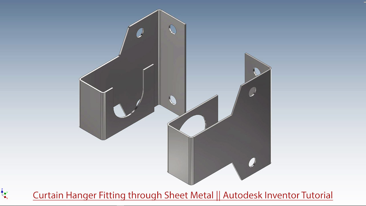
Curtain Hanger Fitting through Sheet Metal (Autodesk Inventor 2018 Tutorial)

Serial No. 324.

In this video create the first by using sheet metal features that will utilize Contour Flange, Cutout and Flat pattern and afterwards we will create an assembly and create a Supporting Steel pipe.


Click the following link to get the model file: - https://bit.ly/3CK9LcH


....................................................................................................
Visit the following link to watch the basic tutorial on Autodesk Inventor by us
https://www.youtube.com/playlist?list=PLb-IhKRMYSERYpB48aY-sZ10fN6CfXIL4
.........................................................................
To watch detailed tutorials on the same software visit the following link
https://www.youtube.com/playlist?list=PL74BDF7431ED13443
..........................................................................................
Hope all of you enjoyed the tutorial. If you find the video useful please like it and share it with your friends/colleagues and do not forget to subscribe us to get latest updates about our new uploads.
http://www.youtube.com/user/niveshandnisheeth?sub_confirmation=1
....................................................................................................
Dear Viewers if you like our work and wanted to support us, to keep continuing the good work, then become a patron of ours at ‘Patreon’ site. Patreon is a simple way for you to contribute to the creator’s work every month/ every time they release their new work and get rewards in return. Please visit the following link to know all about our work and what we are offering as the reward to our patrons…
https://www.patreon.com/nisheethsri+
Sunday, February 21, 2021

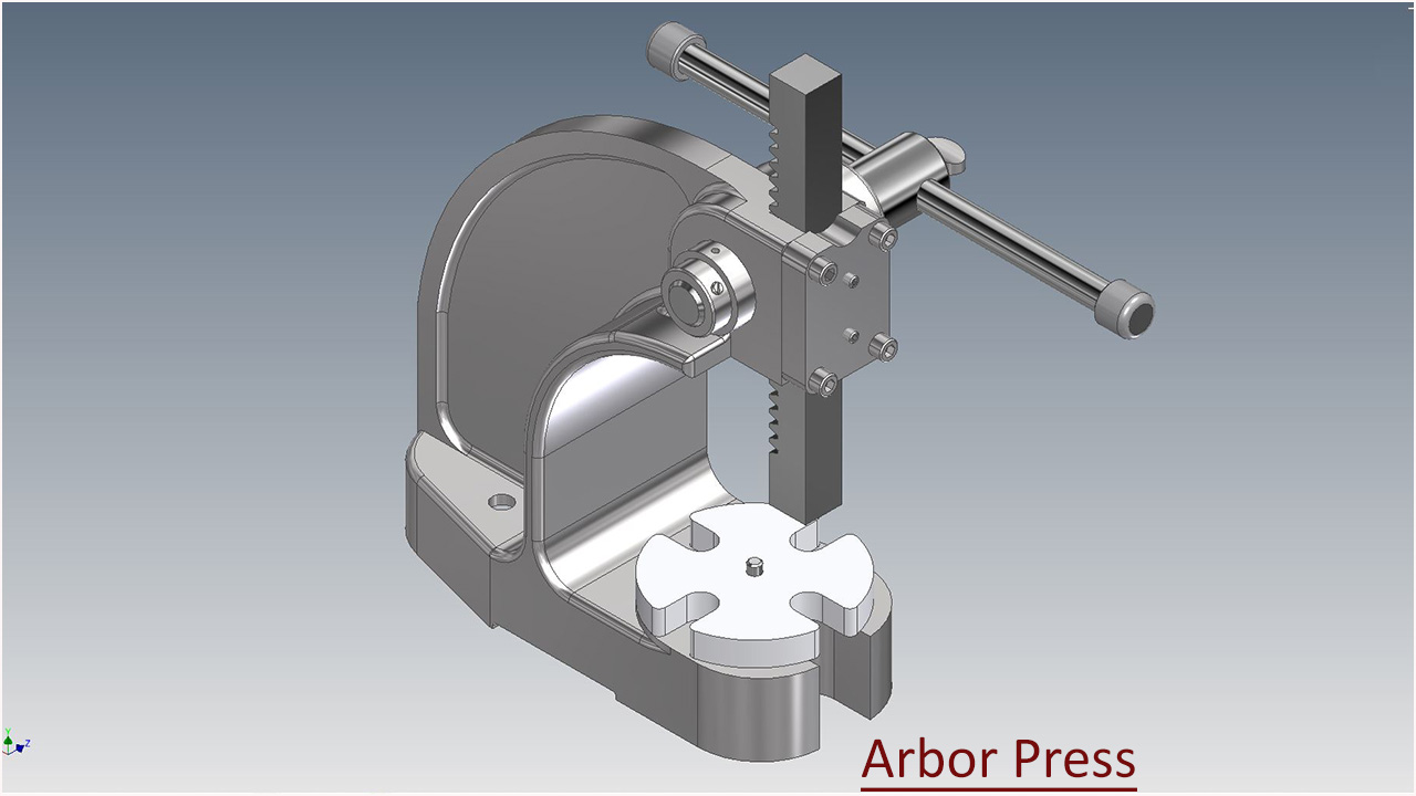
Arbor Press (Autodesk Inventor 2018 Tutorial)

Serial No. 321.

Arbor Press (Autodesk Inventor 2018 Tutorial)

We have added the audio on the entire video so that you can understand this video more easily. This Autodesk Inventor Assembly tutorial which also covers topics from Inventor Basics like sketching and part modelling display a creation process of an assembly named ‘Arbor Press’. This model contains 11 part files and 3 content center files. First, we create the Arbor_Press_frame then later each component is created individually with no relation to each other which you can term the Bottom-up designing process. In this process, the parts are designed individually then inserted into the assembly and setup by using their mates. When the parts have modified the changes also appear in the assembly.


Click the following link to get the model file: - http://bit.ly/2NsNI5U


....................................................................................................
Visit the following link to watch the basic tutorial on Autodesk Inventor by us
https://www.youtube.com/playlist?list=PLb-IhKRMYSERYpB48aY-sZ10fN6CfXIL4
.........................................................................
To watch detailed tutorials on the same software visit the following link
https://www.youtube.com/playlist?list=PL74BDF7431ED13443
..........................................................................................
Hope all of you enjoyed the tutorial. If you find the video useful please like it and share it with your friends/colleagues and do not forget to subscribe us to get latest updates about our new uploads.
http://www.youtube.com/user/niveshandnisheeth?sub_confirmation=1
....................................................................................................
Dear Viewers if you like our work and wanted to support us, to keep continuing the good work, then become a patron of ours at ‘Patreon’ site. Patreon is a simple way for you to contribute to the creator’s work every month/ every time they release their new work and get rewards in return. Please visit the following link to know all about our work and what we are offering as the reward to our patrons…
https://www.patreon.com/nisheethsri+