Showing posts with label Sheet Metal. Show all posts

Thursday, November 4, 2021

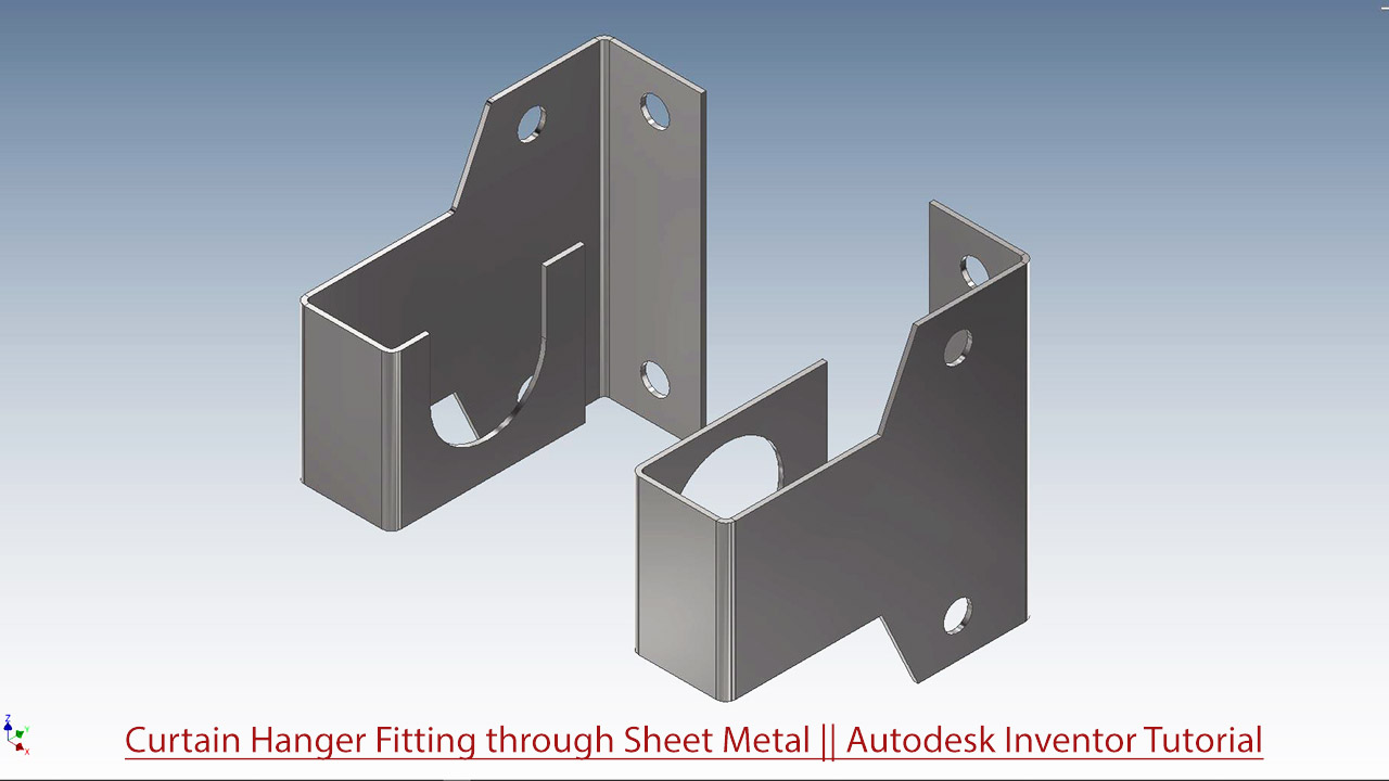
Curtain Hanger Fitting through Sheet Metal (Autodesk Inventor 2018 Tutorial)

Serial No. 324.

In this video create the first by using sheet metal features that will utilize Contour Flange, Cutout and Flat pattern and afterwards we will create an assembly and create a Supporting Steel pipe.


Click the following link to get the model file: - https://bit.ly/3CK9LcH


....................................................................................................
Visit the following link to watch the basic tutorial on Autodesk Inventor by us
https://www.youtube.com/playlist?list=PLb-IhKRMYSERYpB48aY-sZ10fN6CfXIL4
.........................................................................
To watch detailed tutorials on the same software visit the following link
https://www.youtube.com/playlist?list=PL74BDF7431ED13443
..........................................................................................
Hope all of you enjoyed the tutorial. If you find the video useful please like it and share it with your friends/colleagues and do not forget to subscribe us to get latest updates about our new uploads.
http://www.youtube.com/user/niveshandnisheeth?sub_confirmation=1
....................................................................................................
Dear Viewers if you like our work and wanted to support us, to keep continuing the good work, then become a patron of ours at ‘Patreon’ site. Patreon is a simple way for you to contribute to the creator’s work every month/ every time they release their new work and get rewards in return. Please visit the following link to know all about our work and what we are offering as the reward to our patrons…
https://www.patreon.com/nisheethsri+

Tuesday, May 12, 2020

Rectangular_Tub through Sheet Metal (Siemens NX 1855 Tutorial)

Serial No. 132

Rectangular_Tub through Sheet Metal || Siemens NX 1855 Tutorial

Inside this video, we will demonstrate to you how to create a model 'Rectangular_Tub' by using sheet metal designing through Siemens NX Software.
...........................................................................................................
In this lesson, you create a sheet metal part. This lesson demonstrates:
• How to create a custom 'Sheet Metal default settings' before start the sheet metal designing.
• Creating a Tab
• Adding a Flange
• Adding a Contour Flange.
• Adding a Mitre flange by using Contour Flange command.
• Mirroring a feature.
• Adding a cut over the contour flange by using 'Normal Cut-out' command.
• Create a flat pattern feature from the form sheet metal part.


Click the following link to get the model file: - https://bit.ly/2SUHzyU


.........................................................................
Visit the following link to watch more tutorial on Siemens NX by us
https://www.youtube.com/playlist?list=PLKWX3xUP3pPpUvtPuzEPoHimjTjpdbl_Q
.........................................................................
Hope all of you enjoyed the tutorial. If you find the video useful please like it and share it with your friends/colleagues and do not forget to subscribe me to get latest updates about my new uploads….
http://www.youtube.com/user/nisheethsorjm?sub_confirmation=1
....................................................................................................
Dear Viewers if you like our work and wanted to support us, to keep continuing the good work, then become a patron of ours at ‘Patreon’ site. Patreon is a simple way for you to contribute to the creator’s work every month/ every time they release their new work and get rewards in return. Please visit the following link to know all about our work and what we are offering as the reward to our patrons…
https://www.patreon.com/nisheethsri
..................................................................

Tuesday, May 5, 2020

Mounting Bracket through Sheet Metal (Siemens NX 1855 Tutorial)

Serial No. 131

Mounting Bracket through Sheet Metal (Siemens NX 1855 Tutorial)

The Design of this model is selected from 'Sample files' of Autodesk Inventor.

This Siemens NX tutorial displays the modelling process of a 'Mounting Bracket' model which is created by using Sheet Metal functionality.

In this lesson, you create a sheet metal part. This lesson demonstrates:---

  • Creating a base Tab feature.
  • Adding a Flange.
  • Adding a Contour Flange.
  • Adding a Break Corner.
  • Mirroring a sheet metal feature.
  • Adding and bending a tab.
  • Using 'Normal Cut-out' command.
  • Create a flat pattern feature from the form sheet metal part.
  • Create a drawing view of this model by using 'Base View'.
  • Create a drawing view of flat pattern feature.


Click the following link to get the model file: - https://bit.ly/2KUYQUu


.........................................................................
Visit the following link to watch more tutorial on Siemens NX by us
https://www.youtube.com/playlist?list=PLKWX3xUP3pPpUvtPuzEPoHimjTjpdbl_Q
.........................................................................
Hope all of you enjoyed the tutorial. If you find the video useful please like it and share it with your friends/colleagues and do not forget to subscribe me to get latest updates about my new uploads….
http://www.youtube.com/user/nisheethsorjm?sub_confirmation=1
....................................................................................................
Dear Viewers if you like our work and wanted to support us, to keep continuing the good work, then become a patron of ours at ‘Patreon’ site. Patreon is a simple way for you to contribute to the creator’s work every month/ every time they release their new work and get rewards in return. Please visit the following link to know all about our work and what we are offering as the reward to our patrons…
https://www.patreon.com/nisheethsri
..................................................................

Friday, May 1, 2020

Basic Techniques-Sheet Metal (Siemens NX 1855 Tutorial)


Serial No. 130

Basic Techniques-Sheet Metal (Siemens NX 1855 Tutorial)

In this Sheet Metal Tutorial, we will learn the basics of Sheet Metal designing in the software.

In this lesson, you create a sheet metal part. This lesson demonstrates:---

  • Creating a Tab
  • Adding a Flange • Adding a Break Corner
  • Adding a Contour Flange
  • Mirroring the part and creating new bends
  • Mirroring a feature
  • Adding and bending a tab
  • Adding a cut across a bend by using 'Normal Cut-out' command.
  • Folding and unfolding bends by using 'Unbend' & 'Rebend' command.
  • Create a flat pattern feature from the form sheet metal part.
  • Create a drawing view of flat pattern feature.


Click the following link to get the model file: - https://bit.ly/2yhJVkj


.........................................................................
Visit the following link to watch more tutorial on Siemens NX by us
https://www.youtube.com/playlist?list=PLKWX3xUP3pPpUvtPuzEPoHimjTjpdbl_Q
.........................................................................
Hope all of you enjoyed the tutorial. If you find the video useful please like it and share it with your friends/colleagues and do not forget to subscribe me to get latest updates about my new uploads….
http://www.youtube.com/user/nisheethsorjm?sub_confirmation=1
....................................................................................................
Dear Viewers if you like our work and wanted to support us, to keep continuing the good work, then become a patron of ours at ‘Patreon’ site. Patreon is a simple way for you to contribute to the creator’s work every month/ every time they release their new work and get rewards in return. Please visit the following link to know all about our work and what we are offering as the reward to our patrons…
https://www.patreon.com/nisheethsri
..................................................................

Sunday, March 5, 2017

Autodesk Inventor Sheet Metal Tutorial || Project Flat Pattern Command

YouTube-Text-Thumbnail-Temp

This tutorial demonstrates the utilization the Project Flat Pattern Command available in the Sheet Metal modeling environment of Autodesk Inventor. The tool is used to project a selected face or faces of a sheet metal flat pattern onto the active sketch plane.

..............................................................................

Transcription of Video

................................................................................

  1. Here we have a model named Mounting Bracket which is created using Autodesk Inventor’s Sheet Metal functionality. Its two legs have been created using Contour Flange and Face Tool. Now we want to create its third leg by using Face Tool and Fold Tool. Let us see how we will use Project Flat Pattern command in creating third leg.
  2. First of all we need unfolded length of previous leg this can be achieved by using Project Flat Pattern command available in 2D sketching environment.
  3. This is our unfolded projected sketch with the help of this we will create another sketch for the third leg.
  4. On the basis of this sketch we will create an extruded sheet metal face using Face Tool.
  5. Now we need to bend this newly created flat sheet using bend tool.
  6. Again we will utilize the sketch that we got using Project to Flat Pattern Tool to draw new bend lines.
  7. These are the bend lines of previously created leg on basis this we will create our new bend lines.
  8. So now we can easily create our required third leg by folding the visible sheet.
  9. Fully completed model will look like this.

...................................................

Visit the following link to watch full detailed video related to modeling of the Mounting Bracket part

https://www.youtube.com/watch?v=ICPhfxpV9Xg

...................................................

To watch more tutorials related to Autodesk inventor’s sheet metal functionality visit the following link…

https://www.youtube.com/playlist?list=PLKWX3xUP3pPrzu8lASNE9Ol3n7nxlJLG1

..........................................................................................

Hope all of you enjoyed the tutorial. If you find the video useful please like it and share it with your friends/colleagues and do not forget to subscribe us to get latest updates about our new uploads.

http://www.youtube.com/user/nisheethsorjm?sub_confirmation=1

Wednesday, March 1, 2017

Latch created through Sheet Metal (Solid Edge ST9 Tutorial)

Latch

Serial No. 36

Latch created through Sheet Metal (Solid Edge ST9 Tutorial)

In this video creation of an assembly of latch is shown. First Base body parts file of Latch will be created using sheet metal features that will utilize Contour Flange, Tab, Cutout, Rectangular Pattern, Mirror, Break Corner, Flat Pattern tools. Afterwards a Sliding rod part is created with the help of ‘Create Part In-Place’ in context of an assembly to complete it.


download-Link


Click the following link to get the model file: - http://bit.ly/2Vs4Kk9

Thursday, October 13, 2016

Box (mini size) - Video Tutorial (Siemens NX 11)

Box (Mini Size)_1

Box (Mini Size)_2

Serial No. 70.

Box (mini size) - Video Tutorial (Siemens NX 11)

In this Siemens Nx Tutorial we will describe how to build the model of a ‘Box (Mini Size)’ through sheet metal features. It is a part and assembly modeling tutorial, 10 Parts and 3 Assemblies has been created (2 sheet metal parts and 8 other parts) like Box base, Box cover, Wire, Hinge, Sliding and so on in the assembly environment with the help of ‘Create New Component’ command.

It will cover the following topics.

........................................................................................................

• Creating 2D Sketches on different Planes.

• Use the sketch constraints that are applied on during sketch creation.

• Use Sheet metal features such as Tab, Flange, Closed Corner and Flat Pattern.

• Use feature commands such as Extrude, Edge Blend, Mirror feature, Sweep along Guide, Trim body, Unite etc.

• How to set thickness of the sheet and Bend radius by using Sheet Metal Preferences.

• How to create a base feature by extruding a sketch along vector by thickness value by using Tab command.

• How to add a flange at an angle to planar face.

• How to create top-down assembly modelling in Siemens NX software.

• How to remove the degree of freedom of the parts with the help of ‘Assembly Constraints’ command.

• How to rotate the part by using ‘Move Component’ command.

• How to smooth the edges of model by using ‘Visualization Preferences’ command.


download-Link


Click the following link to get the model file: - http://bit.ly/2VqZHk7

Saturday, October 8, 2016

'Stabilizer Cover'-Sheet Metal Modelling-Siemens-NX 11 (Tutorial with Caption)

sheet_metal_model18

Serial No. 69

'Stabilizer Cover'-Sheet Metal Modelling-Siemens-NX 11 (Tutorial with Caption)

The following example shows how to construct the Cover of the Stabilizer with the help of Sheet Metal commands.
____________________________________
This video you will learn:
•    Tab feature
•    Flange Tool
•    Contour Flange
•    Louvers
•    Flat Pattern


download-Link


Click the following link to get the model file: - http://bit.ly/2omwx9M

Wednesday, July 15, 2015

Autodesk Inventor Sheet Metal Tutorial || Contour Roll Tool

Contour Roll Tool

In this tutorial we are going to discuss about the Contour Roll Tool in detail. This tool is used when we want to create a sheet by revolving a profile consisting of lines arcs, splines or elliptical arcs around an axis.

..............................................................................
Transcription of Video
..............................................................................

  1. Here we have a sketch profile which is drawn previously.
  2. Activate Contour Roll tool from the Create Panel of Sheet Metal Tab.
  3. In the Contour Roll Tool Dialogue Box we can see Profile Selection is active.
  4. There are four different options available in Unroll Method.
  5. Let us first see the Centroid Cylinder option.
  6. First select the profile then Axis of revolution.
  7. Here we can see it is telling what would be Neutral Radius and Unfold / Unrolled Length of sheet.
  8. Click Apply button to create the feature.
  9. Activate Create Flat Pattern Tool and check out the extents of the sheets.
  10. The Length mentioned here is the same as it was in the Contour Roll dialogue Box.
  11. Let’s see the another option Custom Cylinder.
  12. Here we have to define Neutral Axis in addition to profile and Axis of revolution.
  13. Here it states that the Unrolled length would be 78.54 mm.
  14. Again check the Unfolded sheet to find the difference.
  15. The next option is the developed length or Unrolled Length…
  16. Here we will fill the same 78.54 length that we got in the Custom Cylinder unroll method.
  17. After defining the Profile and Axis we get the same 50 mm radius of Neutral Axis that is mentioned in our sketch.
  18. In the last method we will only define Neutral Radius along with Profile and Axis.
  19. Here we can see the Unroll Length will be 78.54 if we defining the Neutral Radius to 50mm.

Visit the following link to find some of our popular tutorials on Autodesk Inventor’s Sheet Metal functionality………   http://bit.ly/1JPIa9l

The file shown in the video is taken from the Book ‘Mastering Autodesk Inventor’.

Sunday, September 28, 2014

Chassis for Automatic Voltage Regulator by Sheet Metal (SolidWorks 2014 Tutorial)

Chassis for Automatic Voltage Regulator by Sheet Metal

Serial No. 17

Chassis for Automatic Voltage Regulator by Sheet Metal (SolidWorks 2014 Tutorial)


Inside this video, viewers will watch full detailed process of creating this model through SolidWorks Sheet Metal design functionality.

download-Link


Click the following link to get the model file: - http://bit.ly/2nIgKBQ

Saturday, September 20, 2014

Sheet Metal-Forming Tools (SolidWorks 2014)

Sheet Metal-Forming Tools

Serial No. 16

Sheet Metal-Forming Tools (SolidWorks 2014) 


The Design of this model is selected from 'SolidWorks Tutorials':--

Basic Techniques → Sheet Metal: Forming Tools

You can use preformed sheet metal tools in the Design Library to expedite the forming of details in sheet metal part design.

In this tutorial, you learn the following:

  • Add a formed louver part to the design library.
  • Add a formed louver to a sheet metal part.
  • Select a configuration for the formed louver.
  • Replace the formed louver with a formed extruded hole.
  • Link the formed extruded hole to the sheet metal part to preserve forming tool updates.
  • Set the appearance of placement sketches in flat patterns.
  • Assign punch IDs for use in punch tables.

download-Link


Click the following link to get the model file: - http://bit.ly/2orMAD2

Wednesday, September 17, 2014

Latch created through Sheet Metal (SolidWorks 2014 Tutorial)

Latch

Serial No. 14

Latch created through Sheet Metal (SolidWorks 2014 Tutorial)


In this video creation of an assembly of Latch is shown. First base body parts of latch is created using sheet metal features that will utilize base Flange/Tab, Cut-Extrude, Linear Pattern and Mirror tools. Afterwards a Sliding rod part is created in the assembly to complete it.

download-Link


Click the following link to get the model file: - http://bit.ly/2omYxK0

Tub-Rectangular through Sheet Metal (SolidWorks 2014 Tutorial)

Tub-Rectangular through Sheet Metal

Serial No. 13

Tub-Rectangular through Sheet Metal (SolidWorks 2014 Tutorial)


In this exercise, a Rectangular-Tub is created using Sheet Metal features in SolidWorks. Base-Flange/Tab and Miter Flange are used to create the model, later a drawing sheet of Tub displaying Flat-Pattern is shown with bend line notes.


download-Link


Click the following link to get the model file: - http://bit.ly/2osZnEU

Sunday, September 14, 2014

Basic Techniques-Sheet Metal (SolidWorks 2014 Tutorial)


Serial No. 12

Basic Techniques-Sheet Metal (SolidWorks 2014 Tuitorial)


In this SolidWorks Sheet Metal Tutorial, we will learn the basics of Sheet Metal designing in the software. The tutorial is picked up from the default tutorials that come up with the software. You can find it's written version under  Basic Techniques → Sheet Metal in the software.
Following is the description that is mentioned in the original Tutorial..
In this lesson, you create a sheet metal part. This lesson demonstrates:
  • Creating a base flange
  • Adding a miter flange
  • Mirroring the part and creating new bends
  • Adding an edge flange and editing its sketch profile
  • Mirroring a feature
  • Adding and bending a tab
  • Adding a cut across a bend
  • Folding and unfolding bends
  • Creating a closed corner
  • Creating a sheet metal drawing
  • Adding bend line notes

Video:--


download-Link

Click the following link to get the model file: - http://bit.ly/2ooOX9t


.................................................................................……………
To learn and practice more about Sheet Metal watch videos provided at following playlist..
https://www.youtube.com/playlist?list=PLKWX3xUP3pPrJYXXG2_K2IlquWkPc59lf
...........................................……………………………………………
Visit the following link to watch basic tutorial on SolidWorks by us
https://www.youtube.com/playlist?list=PLb-IhKRMYSES3Zw3QHmQVqQ-rcFVzgYHy
.........................................................................
To watch more detailed tutorials on the same software visit the following link
https://www.youtube.com/playlist?list=PLKWX3xUP3pPo77gFCyy669sI76qJa5jKw
.........................................................................
Hope all of you enjoyed the tutorial. If you find the video useful please like it and share it with your friends/colleagues and do not forget to subscribe us to get latest updates about our new uploads.
http://www.youtube.com/user/niveshandnisheeth?sub_confirmation=1


Sunday, June 29, 2014

Mounting Bracket || Creo Parametric 2.0 Sheet Metal Tutorial

Mounting Bracket Image

In this tutorial I will create a Mounting Bracket by utilizing Sheet Metal capabilities of Creo Parametric 2.0

Mounting Bracket-3 - Copy

First of all base feature will be created using Planar Tool, afterward similar looking legs will be created using various tools like Extrude, Flange,Flat,Bend etc. Usage of Hole, Chamfer Round along with Flat Pattern Tool is also displayed.


Transcription of Video

  1. Start a new Sheet Metal Part file from scratch with the default template and give it a name ‘Mounting Bracket’.

  2. Select the Top Datum plane and create a new sketch on this plane.

  3. Click the Sketch View icon to orient the sketching plane parallel to the screen.

  4. Activate the Circle Tool and draw the sketch with the dimensions as displayed.

  5. Convert this circle into construction geometry.

  6. Create a line in the sketch and duplicate it to the other side, using a centerline with the aid of Mirror Tool.

  7. Draw a new line and repeat the previous process for this line also.

  8. Create arcs between these lines by picking its centre and ends.

  9. Duplicate these arcs to other side using the Mirror Tool.

  10. Exit the sketch and activate Planar Tool.

  11. Fill the thickness of the sheet and execute the command after selecting the sketch.

  12. Change the colour of the model as per your wish.

  13. Create a sketch over Front Datum Plane.

  14. First specify new references, with which new sketch will be constrained and dimensioned.

  15. Draw the sketch using the Line Tool as displayed.

  16. Exit the sketch and activate the Extrude Tool.

  17. Select the sketch and activate Extrude both side of sketch plane equally option.

  18. Fill the extrusion depth.

  19. From the option tab activate add bends on sharp edges command, which would be equal to thickness of the sheet.

  20. Execute the command.

  21. Activate Flange Tool.

  22. Select an edge to attach the wall and then fill the length and angle of the wall.

  23. In the similar way add two more flanges.

  24. Activate the Flat Tool and first specify placement edge.

  25. Execute the command after defining the angle and length of the flat.

  26. Start a new sketch over top face of the model and draw a sketch similar to this one.

  27. First specify new references and use Line to draw the sketch at the defined position.

  28. Activate Bend Tool.

  29. First define the bend line and then fill the bend angle.

  30. Execute the command.

  31. Again repeat the same process to perform another bend operation.

  32. Hide the visibility of sketch3.

  33. Select the leg created with the extrude tool in the model tree and activate Pattern tool.

  34. Open the visibility of Coordinate System.

  35. Set Axis as the type of pattern.

  36. Select Y axis of Coordinate System as axis of rotation.

  37. Enter the number of members to be patterned.

  38. Leave the default 90° Angle between the pattern members unchanged and execute the command.

  39. Save the file.

  40. Apply a Chamfer of 0.125 inch on the each of the legs.

  41. Activate the round tool and apply fillet of .06 inch on these edges of the model.

  42. Create a sketch on the top face of the model and draw a circle on this leg with the defined dimensions.

  43. Create a hole on the leg using this sketch and extrude tool.

  44. Open the visibility of Coordinate System and using its Y axis pattern the hole 4 times at an angle of 90°.

  45. Create a sketch on the top face of the model and create a point to define the position for the new hole.

  46. Activate the Hole Tool and select the point.

  47. Define the diameter of the hole and execute the command.

  48. Pattern this hole 6 times at an angle of 60°using Y axis of Coordinate System.

  49. The model is complete you can generate the Flat Pattern of the model.

Note:--

You may find holes inappropriate created with pattern tool on the leg, it is because the each leg is created with different feature and their flat pattern length is different. To clear this problem, create the holes no each leg separately.

downloadLink_thumb3


Get the Model file by visiting the following link:-
http://bit.ly/2ogQDSk

Thursday, April 10, 2014

Chassis for Constant Voltage Transformer by Sheet Metal (Autodesk Inventor 2013)

Chassis for Constant Voltage Transformer by Sheet Metal

Serial No. 190

Chassis for Constant Voltage Transformer by Sheet Metal (Autodesk Inventor 2013)

Inside this video, viewers will watch full detailed process of creating this model through Autodesk Inventor Software's Sheet Metal design functionality.

download-Link 

Click the following link to get the model file: - http://bit.ly/2nD4jH4

Thursday, March 27, 2014

Chassis for Automatic Voltage Regulator by Sheet Metal (Autodesk Inventor 2013)

Chassis for Automatic Voltage Regulator by Sheet Metal _1

Chassis for Automatic Voltage Regulator by Sheet Metal _2

Serial No. 189

Chassis for Automatic Voltage Regulator by Sheet Metal (Autodesk Inventor 2013)

Inside this video, viewers will watch full detailed process of creating this model through Autodesk Inventor Software's Sheet Metal design functionality .

download-Link 

Click the following link to get the model file: - http://bit.ly/2omQj4E