Showing posts with label SolidWorks Tutorial. Show all posts

Sunday, June 12, 2022

Design a ‘BMW RIM’ in SolidWorks 2017 Tutorial


Capture1

Capture2

Capture3

Capture4


Serial No. 252

Design a ‘BMW RIM’ in SolidWorks 2017 Tutorial

Hello Viewers, Today we will create a model 'BMW RIM' in SolidWorks. This video will be very important for you because today I will tell you how you can easily make this model with the help of Solid Features commands like Revolved Boss/Base with thin feature option, Revolved Cut, Circular Pattern, Fillet and Combine tools. At last, I will place a BMW Logo over its small cover of the Rim under the Edit Appearance by using the Mapping option. You will also learn how to use the Spline Curve in the 2D sketching environment. At all the sure, you will definitely see this video till the end.

I hope you will like this tutorial.


Click the following link to get the model file: - https://bit.ly/3aWbbrL


....................................................................................
Visit the following link to watch the basic tutorial on SolidWorks by us
https://www.youtube.com/playlist?list=PLb-IhKRMYSES3Zw3QHmQVqQ-rcFVzgYHy
.........................................................................
To watch more detailed tutorials on the same software visit the following link
https://www.youtube.com/playlist?list=PLKWX3xUP3pPo77gFCyy669sI76qJa5jKw
...................................................................................
Hope all of you enjoyed the tutorial. If you find the video useful please like it and share it with your friends/colleagues and do not forget to subscribe us to get latest updates about our new uploads.
http://www.youtube.com/user/nisheethsorjm?sub_confirmation=1
....................................................................................................
Dear Viewers if you like our work and wanted to support us, to keep continuing the good work, then become a patron of ours at ‘Patreon’ site. Patreon is a simple way for you to contribute to the creator’s work every month/ every time they release their new work and get rewards in return. Please visit the following link to know all about our work and what we are offering a reward to our patrons…
https://www.patreon.com/nisheethsri
...................................................................................................................................

Friday, May 20, 2022

SolidWorks Surface Modelling 2017 Tutorial || Design a Steel Spoon

Steel_Spoon_1

Steel_Spoon_2

Serial No. 251

SolidWorks Surface Modelling 2017 Tutorial || Design a Steel Spoon

Hello Viewers, Today we will Design a model 'Steel Spoon' with Surface Features in SolidWorks. This video is going to be very important for you because today I will tell you how you can easily make this model with the help of surface tools like "Boundary Surface", "Lofted Surface" and at last, all the surfaces will be converted into a single surface by using the "Knit Surface" command after creating this we will give the Thickness by using the Thicken tool. I hope you will like this tutorial.


Click the following link to get the model file: - https://bit.ly/3lsHEIk


....................................................................................
Visit the following link to watch the basic tutorial on SolidWorks by us
https://www.youtube.com/playlist?list=PLb-IhKRMYSES3Zw3QHmQVqQ-rcFVzgYHy
.........................................................................
To watch more detailed tutorials on the same software visit the following link
https://www.youtube.com/playlist?list=PLKWX3xUP3pPo77gFCyy669sI76qJa5jKw
...................................................................................
Hope all of you enjoyed the tutorial. If you find the video useful please like it and share it with your friends/colleagues and do not forget to subscribe us to get latest updates about our new uploads.
http://www.youtube.com/user/nisheethsorjm?sub_confirmation=1
....................................................................................................
Dear Viewers if you like our work and wanted to support us, to keep continuing the good work, then become a patron of ours at ‘Patreon’ site. Patreon is a simple way for you to contribute to the creator’s work every month/ every time they release their new work and get rewards in return. Please visit the following link to know all about our work and what we are offering a reward to our patrons…
https://www.patreon.com/nisheethsri
...................................................................................................................................

Tuesday, May 3, 2022

Four Cylinder Engine Assembly || SolidWorks 2017 Tutorial


Four Cylinder Engine


Serial No. 250

Four Cylinder Engine Assembly || SolidWorks 2017 Tutorial

Dear Viewers, Today we will design 'Four-Cylinder Engine Assembly' in SolidWorks 2017. This Assembly tutorial covers topics from Solidworks Basics like 2-D sketching and part modeling. The model contains 6 parts like a Crankshaft, Connecting Rod, Piston, etc., and 1 Assembly. First, we create the Crankshaft then later each component is created individually with no relation to each other which you can term the Bottom-up designing process. In this process, the first parts are designed individually, and afterward, all parts are inserted into the assembly by using the assembly constraints. When the parts have been modified the changes also appear in the assembly.


Click the following link to get the model file: - https://bit.ly/3kzQ14d


....................................................................................
Visit the following link to watch the basic tutorial on SolidWorks by us
https://www.youtube.com/playlist?list=PLb-IhKRMYSES3Zw3QHmQVqQ-rcFVzgYHy
.........................................................................
To watch more detailed tutorials on the same software visit the following link
https://www.youtube.com/playlist?list=PLKWX3xUP3pPo77gFCyy669sI76qJa5jKw
...................................................................................
Hope all of you enjoyed the tutorial. If you find the video useful please like it and share it with your friends/colleagues and do not forget to subscribe us to get latest updates about our new uploads.
http://www.youtube.com/user/nisheethsorjm?sub_confirmation=1
....................................................................................................
Dear Viewers if you like our work and wanted to support us, to keep continuing the good work, then become a patron of ours at ‘Patreon’ site. Patreon is a simple way for you to contribute to the creator’s work every month/ every time they release their new work and get rewards in return. Please visit the following link to know all about our work and what we are offering a reward to our patrons…
https://www.patreon.com/nisheethsri
...................................................................................................................................

Saturday, April 30, 2022

Piston Assembly Designing (SolidWorks 2017 Tutorial)

Serial No. 248

Piston Assembly Designing (SolidWorks 2017 Tutorial)

Hi Viewers, Today we will design a model 'Piston' in SolidWorks 2017. In this video, you will learn the full modelling process of this model, at the end of this video It would be placed in the Connecting Rod Assembly.

This Video will cover:-

1. Create basic 2D sketches on different work planes like Front, Top and Right with the help of Line, Circle, Rectangle and 3 Point Arc tools etc.

2. Create a solid feature by using the Extrude Boss/Base, Extruded Cut, Revolve Boss/Base, Revolve Cut, Fillet, Mirror Feature and Chamfer commands.

3. Place the part in Assembly by using the Insert Components. 4. Use the 'Mate' command to position two components relative to one another by using such as Coincident Mate, Concentric mates etc.

Hope all of you enjoyed the tutorial.


Click the following link to get the model file: - https://bit.ly/3KAbbtw


....................................................................................
Visit the following link to watch the basic tutorial on SolidWorks by us
https://www.youtube.com/playlist?list=PLb-IhKRMYSES3Zw3QHmQVqQ-rcFVzgYHy
.........................................................................
To watch more detailed tutorials on the same software visit the following link
https://www.youtube.com/playlist?list=PLKWX3xUP3pPo77gFCyy669sI76qJa5jKw
...................................................................................
Hope all of you enjoyed the tutorial. If you find the video useful please like it and share it with your friends/colleagues and do not forget to subscribe us to get latest updates about our new uploads.
http://www.youtube.com/user/nisheethsorjm?sub_confirmation=1
....................................................................................................
Dear Viewers if you like our work and wanted to support us, to keep continuing the good work, then become a patron of ours at ‘Patreon’ site. Patreon is a simple way for you to contribute to the creator’s work every month/ every time they release their new work and get rewards in return. Please visit the following link to know all about our work and what we are offering a reward to our patrons…
https://www.patreon.com/nisheethsri
...................................................................................................................................

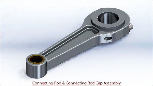
Connecting Rod and Connecting Rod Cap Assembly (SolidWorks 2017 Tutorial)

Serial No. 247

Connecting Rod and Connecting Rod Cap Assembly (SolidWorks 2017 Tutorial)

Hi Viewers, Today we will design two models 'Connecting Rod and Connecting Rod Cap' in SolidWorks 2017. In this video, you will learn the full modelling process of these models and afterwards, we will place components in the Assembly.

This Video will cover:

1. Create basic 2D sketches on different work planes like Front, Top and Right with the help of Line, Circle, and Rectangle tools.

2. Create a solid feature by using the Extrude Boss/Base, Extruded Cut, Revolve Boss/Base, Swept Cut, Fillet, Hole, Mirror Feature and Chamfer commands.

Hope all of you enjoyed the tutorial.


Click the following link to get the model file: - https://bit.ly/3vFShMs


....................................................................................
Visit the following link to watch the basic tutorial on SolidWorks by us
https://www.youtube.com/playlist?list=PLb-IhKRMYSES3Zw3QHmQVqQ-rcFVzgYHy
.........................................................................
To watch more detailed tutorials on the same software visit the following link
https://www.youtube.com/playlist?list=PLKWX3xUP3pPo77gFCyy669sI76qJa5jKw
...................................................................................
Hope all of you enjoyed the tutorial. If you find the video useful please like it and share it with your friends/colleagues and do not forget to subscribe us to get latest updates about our new uploads.
http://www.youtube.com/user/nisheethsorjm?sub_confirmation=1
....................................................................................................
Dear Viewers if you like our work and wanted to support us, to keep continuing the good work, then become a patron of ours at ‘Patreon’ site. Patreon is a simple way for you to contribute to the creator’s work every month/ every time they release their new work and get rewards in return. Please visit the following link to know all about our work and what we are offering a reward to our patrons…
https://www.patreon.com/nisheethsri
...................................................................................................................................
Friday, January 15, 2021

Arbor Press (SolidWorks 2017 Tutorial)

Serial No. 243

Arbor Press (SolidWorks 2017 Tutorial)

We have added the audio on this video so that you can understand it this video more easily. This Solidworks Assembly tutorial which also covers topics from Solidworks Basics like sketching and part modelling display a creation process of an assembly named ‘Arbor Press’. The model contains 10 part files. First, we create the Arbor frame then later each component is created individually with no relation to each other which you can term Bottom-up designing process. In this process, first parts are designed individually then inserted into the assembly and setup by using the mates. When the parts have modified the changes also appear in the assembly.


Click the following link to get the model file: -http://bit.ly/2KiI9FR


....................................................................................
Visit the following link to watch the basic tutorial on SolidWorks by us
https://www.youtube.com/playlist?list=PLb-IhKRMYSES3Zw3QHmQVqQ-rcFVzgYHy
.........................................................................
To watch more detailed tutorials on the same software visit the following link
https://www.youtube.com/playlist?list=PLKWX3xUP3pPo77gFCyy669sI76qJa5jKw
...................................................................................
Hope all of you enjoyed the tutorial. If you find the video useful please like it and share it with your friends/colleagues and do not forget to subscribe us to get latest updates about our new uploads.
http://www.youtube.com/user/nisheethsorjm?sub_confirmation=1
....................................................................................................
Dear Viewers if you like our work and wanted to support us, to keep continuing the good work, then become a patron of ours at ‘Patreon’ site. Patreon is a simple way for you to contribute to the creator’s work every month/ every time they release their new work and get rewards in return. Please visit the following link to know all about our work and what we are offering a reward to our patrons…
https://www.patreon.com/nisheethsri
...................................................................................................................................

Monday, December 14, 2020

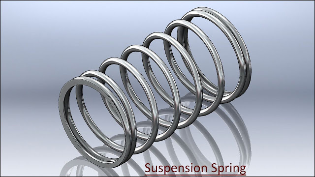
Suspension Spring (SolidWorks 2017 Tutorial)


Serial No. 242

Suspension Spring (SolidWorks 2017 Tutorial)

Today we will create a model 'Suspension Spring' in SolidWorks. Which is taken of our model Suspension Assembly. Full assembly video link is on here:- https://youtu.be/6ukIfhEjlNw


Click the following link to get the model file: - https://bit.ly/37dg9Mi


....................................................................................
Visit the following link to watch the basic tutorial on SolidWorks by us
https://www.youtube.com/playlist?list=PLb-IhKRMYSES3Zw3QHmQVqQ-rcFVzgYHy
.........................................................................
To watch more detailed tutorials on the same software visit the following link
https://www.youtube.com/playlist?list=PLKWX3xUP3pPo77gFCyy669sI76qJa5jKw
...................................................................................
Hope all of you enjoyed the tutorial. If you find the video useful please like it and share it with your friends/colleagues and do not forget to subscribe us to get latest updates about our new uploads.
http://www.youtube.com/user/nisheethsorjm?sub_confirmation=1
....................................................................................................
Dear Viewers if you like our work and wanted to support us, to keep continuing the good work, then become a patron of ours at ‘Patreon’ site. Patreon is a simple way for you to contribute to the creator’s work every month/ every time they release their new work and get rewards in return. Please visit the following link to know all about our work and what we are offering a reward to our patrons…
https://www.patreon.com/nisheethsri
...................................................................................................................................

Monday, August 10, 2020

Create a simple Mould Design Assembly (SolidWorks 2017 Tutorial)

Serial No. 241

Create a simple Mould Design Assembly (SolidWorks 2017 Tutorial)

Today we will create a simple Mold design assembly in SolidWorks. In this video, I will tell you that if you create a new part and merge that part into another solid part, then how will a new mold be formed? First of all, we will create two-part files, as I have shown you in the image before starting this video and then afterwards we will place them into the assembly. At the end of this video, we will merge the first part into the second part by using 'Cavity' command in the SolidWorks Assembly environment. I hope you will enjoy this video.


Click the following link to get the model file: - https://bit.ly/2DuePZG


.....................................................................................
Visit the following link to watch the basic tutorial on SolidWorks by us
https://www.youtube.com/playlist?list=PLb-IhKRMYSES3Zw3QHmQVqQ-rcFVzgYHy
.........................................................................
To watch more detailed tutorials on the same software visit the following link
https://www.youtube.com/playlist?list=PLKWX3xUP3pPo77gFCyy669sI76qJa5jKw
...................................................................................
Hope all of you enjoyed the tutorial. If you find the video useful please like it and share it with your friends/colleagues and do not forget to subscribe us to get latest updates about our new uploads.
http://www.youtube.com/user/nisheethsorjm?sub_confirmation=1
....................................................................................................
Dear Viewers if you like our work and wanted to support us, to keep continuing the good work, then become a patron of ours at ‘Patreon’ site. Patreon is a simple way for you to contribute to the creator’s work every month/ every time they release their new work and get rewards in return. Please visit the following link to know all about our work and what we are offering a reward to our patrons…
https://www.patreon.com/nisheethsri
...................................................................................................................................

Friday, January 3, 2020

Oil Lamp Stand (SolidWorks 2017 Tutorial)

Serial No. 229

Oil Lamp Stand (SolidWorks 2017 Tutorial)

Dear Viewers, In this video we will show how to create an 'Oil Lamp Stand' in SolidWorks Software. We will tell you how to create a 'Lofted Boss/Base' & 'Lofted Cut' feature with Start/End constraints option for making the lampstand.


Click the following link to get the model file: - http://bit.ly/39uT1rR


Our motive to upload this video is to show our workability/experience and to share our knowledge with the viewers and learners.
...........................................................................................
Visit the following link to watch the basic tutorial on SolidWorks by us
https://www.youtube.com/playlist?list=PLb-IhKRMYSES3Zw3QHmQVqQ-rcFVzgYHy
.........................................................................
To watch more detailed tutorials on the same software visit the following link
https://www.youtube.com/playlist?list=PLKWX3xUP3pPo77gFCyy669sI76qJa5jKw
...................................................................................
Hope all of you enjoyed the tutorial. If you find the video useful please like it and share it with your friends/colleagues and do not forget to subscribe us to get latest updates about our new uploads.
http://www.youtube.com/user/nisheethsorjm?sub_confirmation=1
....................................................................................................
Dear Viewers if you like our work and wanted to support us, to keep continuing the good work, then become a patron of ours at ‘Patreon’ site. Patreon is a simple way for you to contribute to the creator’s work every month/ every time they release their new work and get rewards in return. Please visit the following link to know all about our work and what we are offering a reward to our patrons…
https://www.patreon.com/nisheethsri

Saturday, July 27, 2019

Door Stopper (SolidWorks 2017 Tutorial)

Serial No. 226

Door Stopper (SolidWorks 2017 Tutorial)

Door Panel with Hardware Fittings Assembly is brought from my model which was previously uploaded on my channel. We fixed the Door Stopper on this Door Assembly to show its applicability.……………………………………………………………………………………………………………………………………………..
If you want to see the full modelling video of the ‘Door Panel with Hardware Fittings’ Assembly, I mentioned a video link of this model:- http://youtu.be/H9rK3_l-ULs

VIDEO:--


Click the following link to get the model file: - http://bit.ly/2AIiiyy


...........................................................................................
Visit the following link to watch the basic tutorial on SolidWorks by us
https://www.youtube.com/playlist?list=PLb-IhKRMYSES3Zw3QHmQVqQ-rcFVzgYHy
.........................................................................
To watch more detailed tutorials on the same software visit the following link
https://www.youtube.com/playlist?list=PLKWX3xUP3pPo77gFCyy669sI76qJa5jKw
...................................................................................
Hope all of you enjoyed the tutorial. If you find the video useful please like it and share it with your friends/colleagues and do not forget to subscribe us to get latest updates about our new uploads.
http://www.youtube.com/user/nisheethsorjm?sub_confirmation=1
....................................................................................................
Dear Viewers if you like our work and wanted to support us, to keep continuing the good work, then become a patron of ours at ‘Patreon’ site. Patreon is a simple way for you to contribute to the creator’s work every month/ every time they release their new work and get rewards in return. Please visit the following link to know all about our work and what we are offering a reward to our patrons…
https://www.patreon.com/nisheethsri
.............................................................................


#solidworks #solidworkstutorial #solidworksassembly #solidworks #solidworkspart

Sunday, June 30, 2019

Door Security Bar (SolidWorks 2017 Tutorial)

Serial No. 225

Door Security Bar (SolidWorks 2017 Tutorial)

Door Panel with Hardware Fittings Assembly is brought from my model which was previously uploaded on my channel. We fixed the Door Security Bar on this Door Assembly to show its applicability.
If you want to see the full modelling video of the Door Panel with Hardware Fittings Assembly, I mentioned a video link of this model:- http://youtu.be/H9rK3_l-ULs

VIDEO:--


Click the following link to get the model file: - http://bit.ly/2Omf3F6


...........................................................................................
Visit the following link to watch the basic tutorial on SolidWorks by us
https://www.youtube.com/playlist?list=PLb-IhKRMYSES3Zw3QHmQVqQ-rcFVzgYHy
.........................................................................
To watch more detailed tutorials on the same software visit the following link
https://www.youtube.com/playlist?list=PLKWX3xUP3pPo77gFCyy669sI76qJa5jKw
...................................................................................
Hope all of you enjoyed the tutorial. If you find the video useful please like it and share it with your friends/colleagues and do not forget to subscribe us to get latest updates about our new uploads.
http://www.youtube.com/user/nisheethsorjm?sub_confirmation=1
....................................................................................................
Dear Viewers if you like our work and wanted to support us, to keep continuing the good work, then become a patron of ours at ‘Patreon’ site. Patreon is a simple way for you to contribute to the creator’s work every month/ every time they release their new work and get rewards in return. Please visit the following link to know all about our work and what we are offering a reward to our patrons…
https://www.patreon.com/nisheethsri

Saturday, January 19, 2019

'Vernier Caliper' (Volume-1) SolidWorks 2017 Tutorial


Serial No. 223-A


'Vernier Caliper' (Volume-1) SolidWorks 2017 Tutorial
(Rest of the model is designed in Volume-2 & 3)


 https://autode.sk/2FJZcMb


Click the following link to get the model file: - http://bit.ly/2oRyACK


The Procedure of reading of Vernier Caliper in Millimetre Scale
Total number of divisions imprinted on Linear Scale = 150
Total number of divisions imprinted on Vernier Scale = 50
Pitch of Linear Scale = total length of Linear scale/total number of divisions imprinted on
                                       Linear scale
                                    = 150 mm / 150 = 1 mm
Least count of Vernier Scale = Pitch of Linear scale / Total number of divisions on Vernier Scale
                                                = 1 mm / 50 = 0.02 mm
Reading of Linear Scale = Pitch of Linear scale x Number of divisions on Linear Scale just before the
                                             zero of Vernier Scale
                                          = 1 mm x 12 = 12 mm
Reading of Vernier Scale = Least count of Vernier Scale x Number of divisions of Vernier Scale
                                              aligned with the marking of Linear Scale
                                           = 0.02 mm x 28 = 0.56 mm
Total Reading = Reading of Linear Scale + Reading of Vernier Scale
                         = 12 mm + 0.56 mm = 12.56 mm = 1.256 cm
__________________________________________________________________
Procedure of reading of Vernier Caliper in Inch Scale
Total number of divisions imprinted on Linear Scale  = 240
Total number of divisions imprinted on Vernier Scale = 25
Pitch of Linear Scale = total length of Linear scale/total number of divisions imprinted
                                        on Linear scale
                                     = 6 inch / 240= 0.025 inch
Least count of Vernier Scale = Pitch of Linear Scale / Total number of divisions on Vernier scale
                                                = 0.025 inch / 25 = 0.001 inch
Reading of Linear Scale = Pitch of Linear scale x Number of divisions on Linear Scale just before the
                                             zero of Vernier Scale
                                          = 0.025 inch x 45 = 1.125 inch
Reading of Vernier Scale = Least count of Vernier Scale x Number of divisions of Vernier Scale
                                              aligned with the marking of Linear Scale
                                           = 0.001 inch x 14 = 0.014 inch
Total Reading = Reading of Linear Scale + Reading of Vernier Scale
                         = 1.125 inch + 0.014 inch = 1.139 inch


'Vernier Caliper' (Volume-2) SolidWorks 2017 Tutorial


Serial No. 223-B


'Vernier Caliper' (Volume-2) SolidWorks 2017 Tutorial
(Rest of the model is designed in Volume-1 & 3)


 https://autode.sk/2FJZcMb


Click the following link to get the model file: - http://bit.ly/2oRyACK


The Procedure of reading of Vernier Caliper in Millimetre Scale
Total number of divisions imprinted on Linear Scale = 150
Total number of divisions imprinted on Vernier Scale = 50
Pitch of Linear Scale = total length of Linear scale/total number of divisions imprinted on
                                       Linear scale
                                    = 150 mm / 150 = 1 mm
Least count of Vernier Scale = Pitch of Linear scale / Total number of divisions on Vernier Scale
                                                = 1 mm / 50 = 0.02 mm
Reading of Linear Scale = Pitch of Linear scale x Number of divisions on Linear Scale just before the
                                             zero of Vernier Scale
                                          = 1 mm x 12 = 12 mm
Reading of Vernier Scale = Least count of Vernier Scale x Number of divisions of Vernier Scale
                                              aligned with the marking of Linear Scale
                                           = 0.02 mm x 28 = 0.56 mm
Total Reading = Reading of Linear Scale + Reading of Vernier Scale
                         = 12 mm + 0.56 mm = 12.56 mm = 1.256 cm
__________________________________________________________________
Procedure of reading of Vernier Caliper in Inch Scale
Total number of divisions imprinted on Linear Scale  = 240
Total number of divisions imprinted on Vernier Scale = 25
Pitch of Linear Scale = total length of Linear scale/total number of divisions imprinted
                                        on Linear scale
                                     = 6 inch / 240= 0.025 inch
Least count of Vernier Scale = Pitch of Linear Scale / Total number of divisions on Vernier scale
                                                = 0.025 inch / 25 = 0.001 inch
Reading of Linear Scale = Pitch of Linear scale x Number of divisions on Linear Scale just before the
                                             zero of Vernier Scale
                                          = 0.025 inch x 45 = 1.125 inch
Reading of Vernier Scale = Least count of Vernier Scale x Number of divisions of Vernier Scale
                                              aligned with the marking of Linear Scale
                                           = 0.001 inch x 14 = 0.014 inch
Total Reading = Reading of Linear Scale + Reading of Vernier Scale
                         = 1.125 inch + 0.014 inch = 1.139 inch

Thursday, September 6, 2018

Creating a custom template in Solid Works 2017 (with caption and audio narration)

Creating a custom template in Solid Edge ST9

Serial No. 222

Creating a custom template in Solid Works 2017 (with caption and audio narration)


Transcription of the Video

  1. Create the new part in SolidWorks 2017 software.
  2. 'Trimetric' view is selected by default, choose 'Isometric' view.
  3. Create a new sketch over front plane.
  4. Draw a sketch and apply the dimension.
  5. Activate the 'Edit Document Units' button.
  6. In the Unit system section, select the 'Custom' button.
  7. Change the decimal value up to 3 places (under Basic Units → Length).
  8. If you want to measure linear length in two different units (i.e. millimetres and inches), then go to the Dual Dimension Length and select decimal value up to 3 places.
  9. Activate the Smart Dimension tool and apply on 'Dual Dimension' option.
  10. Once again activate the 'Edit Document Units' button.
  11. Set the fraction value 32(under Basic Units → Length).
  12. Click OK.
  13. Save this file by using 'Save As' command.
  14. In the 'Save as type' section, choose 'Part Templates' option.
  15. Save the template file by giving it proper name, in a SolidWorks template folder.
  16. Reopen the previously created template file to watch the effect.

Tuesday, January 30, 2018

Animation displayed in 'Vise' Assembly--SolidWorks 2017 (with caption and audio narration)

SolidWorks Animation Tutorial ‘Vise’ Assembly_1

SolidWorks Animation Tutorial ‘Vise’ Assembly_2

Serial No. 220

Animation displayed in 'Vise' Assembly--SolidWorks 2017 (with caption and audio narration)

To watch full sketching video of this model 'Vise', please visit my another associated video named as 'Vise' (Video Tutorial --- Volume-1 and 2) SolidWorks.

download-Link


Click the following link to get the model file: - http://bit.ly/2VffJ0i


Transcription of the Video

  1. Create a new assembly within an English template.
  2. The ‘Begin Assembly’ command is already activated in the assembly design window.
  3. Browse the ‘Part1’ file from the Vise → ‘Subassembly-1’ folder, here select ‘Part1’ file and open it.
  4. Go to the ‘View (Heads-Up)’ toolbar, click on the ‘Visibility Off’ icon.
  5. Turn on the ‘View Origins’ button, the assembly origin button will be visible in the assembly design window.
  6. Place the ‘Part1’ file over the assembly origin.
  7. Now the ‘Part1’ file has fixed in the centre of the assembly.
  8. Choose Isometric view.
  9. Turn off the ‘View Origins’ button.
  10. Save the assembly, name it as ‘Subassembly1’.
  11. Activate the ‘Insert Components’ command and place the ‘Part2’ file in the assembly.
  12. Apply a ‘Coincident’ mate between the selected face of ‘Part1’ and selected face of ‘Part2’.
  13. Apply a ‘Coincident’ mate between the Right Plane of ‘Part1’ & Right Plane of ‘Part2’.
  14. Activate the ‘Mate’ command, choose ‘Distance’ option in the ‘Standard Mates’ section.
  15. Fill value 5.672 inches in the Distance input box and select the face of ‘Part1’ and select the face of ‘Part2’.
  16. Click Ok to apply the Distance mate.
  17. Now the ‘Part2’ file is fixed on the base of ‘Part1’, it can’t be moved.
  18. Save the subassembly.
  19. Place the ‘Part3’ file in the assembly by using ‘Insert Components’ command.
  20. Apply a ‘Coincident’ mate between the slotted face of ‘Part1’ and back face of ‘Part3’.
  21. Apply a ‘Coincident’ mate between the slotted face of ‘Part1’ & selected face of ‘Part3’ file.
  22. Apply a ‘Coincident’ mate between the side face of ‘Part3’ & side face of ‘Part1’ file.
  23. Now the ‘Part3’ component is fixed over the slot of ‘Part1’, it can’t rotate or drag it.
  24. Go to the ‘Task Pane’ tab, choose the ‘Design Library’ button and select the ‘Toolbox’ icon.
  25. Click ‘Add-in now’ button, here more types of ‘component standards’ are available, select one of them according to your choice.
  26. Open ‘ANSI Inch’ standard folder, next click ‘Bolts and Screws’ folder.
  27. Next click the ‘Countersunk Head’ folder and select ‘Countersunk Bolt’ item.
  28. Drag the bolt in graphics area of the assembly as shown.
  29. Select 5/16-18 from the Size area and set the length value to 0.875inch.
  30. Click OK to accept it and place one more similar bolt, click OK to finish the command.
  31. Apply a Concentric mate between the cylindrical face of ‘Countersunk bolt’ & hole of ‘Part3’.
  32. Go to the ‘Mates’ folder in the Model Tree, edit the ‘Concentric1’ mate and activate the ‘Lock Rotation’ button to stop the rotation of the bolt.
  33. Apply a Coincident mate between the selected face of the bolt and selected face of ‘Part3’.
  34. In the same way, fix another countersunk bolt over the second hole of ‘Part3’ by using ‘Mate’ command.
  35. Change the colour of bolts ‘Polished Brass’, it looks good.
  36. Save the ‘Subassembly1’.
  37. Close the ‘Subassembly1’.
  38. Create a new assembly file.
  39. Browse the ‘Part4’ file in the ‘Subassembly-2’ folder, select ‘Part4’ file and open it.
  40. Fix the aforesaid part in the assembly origin as stated in the previous section.
  41. Go to the View Cube and choose Isometric View.
  42. Activate the ‘Insert Components’ command and place the ‘Part5’ file in the assembly.
  43. Apply a ‘Coincident’ mate between the slotted face of ‘Part4’ and back face of ‘Part5’.
  44. Apply a ‘Coincident’ mate between the slotted face of ‘Part4’ & selected face of ‘Part5’ file.
  45. Apply a ‘Coincident’ mate between the side face of ‘Part5’ & side face of ‘Part4’ file.
  46. Save the assembly, name it as ‘Subassembly-2’.
  47. Place the two countersunk bolts from the SolidWorks Design Library which was explained earlier.
  48. Apply a Concentric mate between the cylindrical face of ‘Countersunk bolt’ & hole of ‘Part5’.
  49. Choose ‘Lock Rotation’ option.
  50. Apply a Coincident mate between the selected face of the bolt and selected face of ‘Part5’.
  51. In the same way, fix another countersunk bolt over the second hole of ‘Part5’ by using ‘Mate’ command.
  52. Change the colour of bolts ‘Polished Brass’, it looks good.
  53. Close the ‘Subassembly-2’.
  54. Create a new assembly file.
  55. Browse the ‘Part6’ file in the ‘Subassembly-3’ folder, select ‘Part6’ file and open it.
  56. Fix the aforesaid part in the assembly origin.
  57. Save the assembly, name it as ‘Subassembly-3’.
  58. Place the ‘Handle’ in the assembly.
  59. Apply a Concentric mate between the cylindrical face of ‘Handle’ & hole of ‘Part6’.
  60. Apply a Coincident mate between the Top Plane of ‘Part6’ and Front Plane of ‘Handle’.
  61. Now the Handle is fixed on the ‘Part6’ file, it can’t drag it.
  62. Go to the ‘Mates’ folder and edit the ‘Concentric1’ mate, choose ‘Lock Rotation’ option.
  63. Click Ok to finish the command.
  64. Save the assembly.
  65. Place the ‘Spring’ in the assembly.
  66. Change the colour of Spring ‘Brushed Aluminum’, it looks good.
  67. Go to the ‘View’ tab → select ‘Hide/Show’ button → click on ‘Axes’ icon.
  68. Open the visibility of ‘Axis1’ of Spring.
  69. Now the ‘Axis1’ of spring is visible in the assembly design window.
  70. Apply a Concentric mate between the Axis1 of ‘Spring’ & cylindrical face of ‘Part6’.
  71. Apply a Coincident mate between the circular face of ‘Part6’ & selected face of ‘Spring’.
  72. Turn-off the ‘Axes’ button.
  73. Insert the ‘Washer’ & ‘Pin’ in the assembly.
  74. Apply a Concentric mate between the hole of ‘Washer’ & cylindrical face of ‘Part6’.
  75. Apply a Coincident mate between the selected face of the Spring and selected face of ‘Washer’.
  76. Fix the Pin on the hole of ‘Part6’ by the aid of ‘Mate’ command.
  77. Now the subassembly is complete, save and close it.
  78. Create a new assembly within an English template.
  79. It is a main assembly to create the animation of Vise. Here three subassemblies will be placed which were created earlier.
  80. Browse the ‘Subassembly-1’ and open it.
  81. Place the ‘Subassembly-1’ on the assembly origin.
  82. Now the ‘Subassembly-1’ is fixed in the centre of the assembly.
  83. Choose Isometric view.
  84. Save the assembly, name it as ‘Vise with Animation’.
  85. Insert the ‘Subassembly-2’ in the assembly design area.
  86. Rotate the ‘Subassembly-2’ in front of ‘SubAssembly-1’ by using ‘Move with Triad’ tool.
  87. Apply a Coincident mate between the bed of ‘Subassembly-1’ and the bottom face of ‘Subassembly-2’.
  88. Apply a Coincident mate between the Right Plane of ‘Subassembly-1’ and Front Plane of ‘Subassembly-2’.
  89. Drag the ‘Subassembly-2’ to see the result, it can run on the bed of ‘Subassembly-1’.
  90. Insert the ‘Subassembly-3’ in the assembly design window.
  91. Rotate the ‘Subassembly-3’ in front of ‘SubAssembly-1’ by using ‘Move with Triad’ tool.
  92. Pick-up the ‘Part6’ & ‘Part2’ from the Model Tree, right-click and choose ‘Isolate’ option.
  93. Go to the ‘View’ tab → select ‘Hide/Show’ button → click on ‘Temporary Axes’ icon.
  94. Now the Axes of ‘Part6’ & ‘Part2’ are visible in the assembly design window.
  95. Activate the ‘Mate’ command, go to the ‘Mechanical Mates’ tab in the Mate dialogue box.
  96. Different types of mechanical mates are available here, choose any suitable mate according to need of the design.
  97. In this case we have selected ‘Screw’ mate button.
  98. Choose ‘Distance/revolution’ option and select the Axis of ‘Part6’ & Axis of ‘Part2’.
  99. Fill the value 1/7 inch in the ‘Distance/revolution’ input box, it will be designated by the ‘Mate Selections’ area.
  100. Click OK to execute the ‘Screw Mate’ command.
  101. Switch-off the ‘Temporary Axes’ button.
  102. Disable the ‘Exit Isolate’ button.
  103. Apply a Coincident mate between the circular face of ‘Part4’ and circular face of ‘Part6’.
  104. Rotate the Handle of Vise to examine the working of ‘Screw Mate’.
  105. When the Handle is rotated either in clockwise or anticlockwise direction, the ‘Subassembly-2’ will run closure or farther from the ‘Subassembly-1’.
  106. Activate the ‘Mate’ command, choose ‘Distance’ mate button.
  107. Set the value at 0 and select Jaw faces of ‘Subassembly-1’ & ‘Subassembly-2’.
  108. Click OK to finish the command.
  109. Go to the ‘Motion Study1’ tab and expand the animation timeline.
  110. Move the timebar at 1.5 second and go to the ‘Mates’ folder.
  111. Place a new key adjacent to ‘Distance1’ mate by the aid of ‘Place Key’ command.
  112. Move the timebar at 21.5 second and add a new key.
  113. Edit the ‘Distance1’ mate key and set the value 1inch in the Modify dialogue box.
  114. Click OK to accept it.
  115. ‘Subassembly2’ will open from start point 0 to 1 inch and it will consume time from 1.5 sec. to 21.5 sec. (i.e. time taken 20 seconds)
  116. Move the timebar at 29.5 second and place the new key.
  117. Move the timebar at 49.5 second, copy the ‘Distance1’ mate key and paste it.
  118. Now return back ‘Subassembly-2’ from 1 inch to start point 0, in this case time consumed from 29.5 to 49.5 seconds.
  119. Close the Mates folder.
  120. In the next section of this video, we will create two additional views to see different positions of the ‘Vise’.
  121. These saved views will be used next in the animation timeline.
  122. Minimize the animation timeline and clear the screen to see full view of the model.
  123. Set the position of the model in following way.
  124. Choose ‘New View’ button from the ‘Orientation’ dialogue box.
  125. A ‘Named View’ dialogue box will be visible in the design window and change its name as ‘View-1’ and click OK.
  126. Now ‘View1’ is added in the Orientation dialogue box.
  127. In the same manner, rotate the model in opposite side by using View Cube command and save the view name it as ‘View-2’.
  128. Save the assembly and return back to full screen view.
  129. Expand the animation timeline.
  130. Go to the ‘Orientation and Camera Views’ tab, select the ‘Isometric’ key.
  131. Select ‘View-1’ from the ‘Orientation’ dialogue box.
  132. Select the ‘Isometric’ key, right-click and choose ‘Replace Key’ option.
  133. Now the ‘Isometric’ key is replaced from ‘Isometric’ view to ‘View1’ by using ‘Replace Key’ command.
  134. Move the timebar at 23 second and place the new key.
  135. The ‘View-1’ of the model will be in still position from start point 0 to 23 sec. (i.e. time taken 23 seconds)
  136. Move the timebar at 28 second and select ‘View-2’ from the ‘Orientation’ dialogue box.
  137. Place the new key, time consumed 5 seconds from ‘View-1’ to ‘View-2’ position.
  138. Move the timebar at 51 second and place the new key.
  139. The ‘View-2’ of the model will be in still position from 28 to 51 sec. (i.e. time taken 23 seconds).
  140. Move the timebar at 56 second, copy the View-1 key and paste it.
  141. Time taken 5 seconds to return back in previous position of the model.
  142. Move the timebar at 28 second and go to the ‘Subassembly-1’ folder.
  143. Select the ‘Part1’ file and click ‘Add/Update Key’ button.
  144. A new key is added at 28 sec. in the animation timeline.
  145. Move the timebar at 29.5 second, select the ‘Part1’ file.
  146. Activate the ‘Edit Appearance’ command and change the color of ‘Part1’ as reflective green glass.
  147. Click OK to accept it.
  148. The time is taken 1.5 seconds for change the default color to transparent color of ‘Part1’ file.
  149. In the same manner, place two more keys at 49.5 and 51 seconds in the animation timeline.
  150. Go to the ‘Subassembly-2’ folder and select ‘Part4’ file.
  151. In the same manner, change the color of ‘Part4’ as reflective green glass and add 4 new keys at 28, 29.5, 49.5 & 51 seconds in the animation timeline.
  152. Click ‘Calculate’ button to check the animation.
  153. Click ‘Stop’ button, now see here the handle of vise is cut in the assembly design area while running of the animation. It’s not good in practice.
  154. Now we will create a new View and replace ‘View-2’ by this new view with the help of ‘Replace Key’ command.
  155. Set the desired view of the model and develop a new view, name it as ‘View-3’.
  156. And replace the key from ‘View-2’ to ‘View-3’ in the animation timeline.
  157. In the same way, replace another view key.
  158. Finally click calculate button and click ‘Play form Start’ button to observe the animation of ‘Vise’ mechanism.
  159. Save the assembly.
  160. Return back to the Model view.