Showing posts with label Autodesk. Show all posts

Thursday, March 2, 2023

Basic Part Modelling_Ex.1 (Autodesk Inventor 2018 Tutorial)


2


1


Serial No. 339.

Dear Viewers, In this video we will create the part and afterward will generate the drawing sheet of this part, If you want to download the part file or drawing sheet file please visit our blog.

This video will cover the following Topics

• 2D Sketching on YZ, XZ & XY Planes. • Different kinds of Extrude command operations like Join, Cut, Distance, Through All, From & To options.

  • Fillet Tool.

• How to create a simple hole over the part by using the Holt Tool command.

• About the Rib Tool.

How to generate the drawing sheet of this part in this software?

• Place the Base and Projected views of this part in the inventor drawing sheet file.

• Apply the dimension over the views by using the Dimension Tool.

• How to modify the dimension styles & increase the font size of the dimensions under the ‘Style & Standard Editor” in the software.

Hope all of you enjoyed the tutorial.


Click the following link to get the model file: - http://bit.ly/3SGwYW2


....................................................................................................
Visit the following link to watch the basic tutorial on Autodesk Inventor by us
https://www.youtube.com/playlist?list=PLb-IhKRMYSERYpB48aY-sZ10fN6CfXIL4
.........................................................................
To watch detailed tutorials on the same software visit the following link
https://www.youtube.com/playlist?list=PL74BDF7431ED13443
..........................................................................................
Hope all of you enjoyed the tutorial. If you find the video useful please like it and share it with your friends/colleagues and do not forget to subscribe us to get latest updates about our new uploads.
http://www.youtube.com/user/niveshandnisheeth?sub_confirmation=1
....................................................................................................
Dear Viewers if you like our work and wanted to support us, to keep continuing the good work, then become a patron of ours at ‘Patreon’ site. Patreon is a simple way for you to contribute to the creator’s work every month/ every time they release their new work and get rewards in return. Please visit the following link to know all about our work and what we are offering as the reward to our patrons…
https://www.patreon.com/nisheethsri+

Friday, December 27, 2019

Propeller (Autodesk Inventor 2018 Tutorial)

Serial No. 316.

Propeller (Autodesk Inventor 2018 Tutorial)

The Design of ‘Propeller’ has been taken from Assembly of 'Blower' → ‘Sample files’ → Autodesk Inventor. __________________________________________________________

In this Inventor tutorial we will describe how to build the model of ‘Propeller’. It is a part modeling tutorial, it will cover the following topics. ___________________________________________________________

  • Creating 2D Sketches on different Planes of the model.
  • Use the sketch constraints that are applied on during sketch creation.
  • Use feature commands such as Extrude, Extrude with ‘Intersect’ option, Circular Pattern, Revolve Surface, Revolve, Thicken/Offset and the Fillet tool.
  • Use Circular Pattern tool to create multiple instances of one feature.


Click the following link to get the model file: - http://bit.ly/2Qtosdg


....................................................................................................
Visit the following link to watch the basic tutorial on Autodesk Inventor by us
https://www.youtube.com/playlist?list=PLb-IhKRMYSERYpB48aY-sZ10fN6CfXIL4
.........................................................................
To watch detailed tutorials on the same software visit the following link
https://www.youtube.com/playlist?list=PL74BDF7431ED13443
..........................................................................................
Hope all of you enjoyed the tutorial. If you find the video useful please like it and share it with your friends/colleagues and do not forget to subscribe us to get latest updates about our new uploads.
http://www.youtube.com/user/niveshandnisheeth?sub_confirmation=1
....................................................................................................
Dear Viewers if you like our work and wanted to support us, to keep continuing the good work, then become a patron of ours at ‘Patreon’ site. Patreon is a simple way for you to contribute to the creator’s work every month/ every time they release their new work and get rewards in return. Please visit the following link to know all about our work and what we are offering as the reward to our patrons…
https://www.patreon.com/nisheethsri+

Wednesday, May 22, 2019

Generation of Conic Section → Ellipse (Autodesk Inventor 2018 Tutorial)

Serial No. 306

Generation of Conic Section → Ellipse (Autodesk Inventor 2018 Tutorial)

In mathematics, a conic section (or simply conic) is a curve obtained as the intersection of the surface of a cone with a plane. The three types of conic section are the hyperbola, the parabola, and the ellipse; the circle is a special case of the ellipse, though historically it was sometimes called a fourth type.
At the end of this video, we will show how to rotate a sketch of the ellipse to create an Ellipsoid by using the Revolve tool.

Video:--


Click the following link to get the model file: - http://bit.ly/2nmoM3i


Note:-

The finished file related to this tutorial is available to download as mentioned above. But for this send us a formal request on our following email niveshandnisheeth@gmail.com to download it.
...................................................................................
Our motive to upload this video is to show our workability/experience and to share my knowledge with the viewers and learners.

....................................................................................................
Visit the following link to watch the basic tutorial on Autodesk Inventor by us
https://www.youtube.com/playlist?list=PLb-IhKRMYSERYpB48aY-sZ10fN6CfXIL4
.........................................................................
To watch detailed tutorials on the same software visit the following link
https://www.youtube.com/playlist?list=PL74BDF7431ED13443
..........................................................................................
Hope all of you enjoyed the tutorial. If you find the video useful please like it and share it with your friends/colleagues and do not forget to subscribe us to get latest updates about our new uploads.
http://www.youtube.com/user/niveshandnisheeth?sub_confirmation=1
....................................................................................................
Dear Viewers if you like our work and wanted to support us, to keep continuing the good work, then become a patron of ours at ‘Patreon’ site. Patreon is a simple way for you to contribute to the creator’s work every month/ every time they release their new work and get rewards in return. Please visit the following link to know all about our work and what we are offering as the reward to our patrons…
https://www.patreon.com/nisheethsri

Generation of Conic Section → Parabola (Autodesk Inventor 2018 Tutorial)

Serial No. 307

Generation of Conic Section → Parabola (Autodesk Inventor 2018 Tutorial)

In mathematics, a conic section (or simply conic) is a curve obtained as the intersection of the surface of a cone with a plane. The three types of conic section are the hyperbola, the parabola, and the ellipse; the circle is a special case of the ellipse, though historically it was sometimes called a fourth type.
At the end of this video, we will show how to rotate a sketch of the parabola to create a Paraboloid by using the Revolve tool.

Video:--


Click the following link to get the model file: - http://bit.ly/2nzmZro


Note:-

The finished file related to this tutorial is available to download as mentioned above. But for this send us a formal request on our following email niveshandnisheeth@gmail.com to download it.
...................................................................................
Our motive to upload this video is to show our workability/experience and to share my knowledge with the viewers and learners.

....................................................................................................
Visit the following link to watch the basic tutorial on Autodesk Inventor by us
https://www.youtube.com/playlist?list=PLb-IhKRMYSERYpB48aY-sZ10fN6CfXIL4
.........................................................................
To watch detailed tutorials on the same software visit the following link
https://www.youtube.com/playlist?list=PL74BDF7431ED13443
..........................................................................................
Hope all of you enjoyed the tutorial. If you find the video useful please like it and share it with your friends/colleagues and do not forget to subscribe us to get latest updates about our new uploads.
http://www.youtube.com/user/niveshandnisheeth?sub_confirmation=1
....................................................................................................
Dear Viewers if you like our work and wanted to support us, to keep continuing the good work, then become a patron of ours at ‘Patreon’ site. Patreon is a simple way for you to contribute to the creator’s work every month/ every time they release their new work and get rewards in return. Please visit the following link to know all about our work and what we are offering as the reward to our patrons…
https://www.patreon.com/nisheethsri

Generation of Conic Section → Hyperbola (Autodesk Inventor 2018 Tutorial)


Serial No. 308

Generation of Conic Section → Hyperbola (Autodesk Inventor 2018 Tutorial)

In mathematics, a conic section (or simply conic) is a curve obtained as the intersection of the surface of a cone with a plane. The three types of conic section are the hyperbola, the parabola, and the ellipse; the circle is a special case of the ellipse, though historically it was sometimes called a fourth type.
At the end of this video, we will show how to rotate a sketch of the Hyperbola to create a hyperboloid by using the Revolve tool.

Video:--


Click the following link to get the model file: - http://bit.ly/2nwxCvg


Note:-

The finished file related to this tutorial is available to download as mentioned above. But for this send us a formal request on our following email niveshandnisheeth@gmail.com to download it.
...................................................................................
Our motive to upload this video is to show our workability/experience and to share my knowledge with the viewers and learners.

....................................................................................................
Visit the following link to watch the basic tutorial on Autodesk Inventor by us
https://www.youtube.com/playlist?list=PLb-IhKRMYSERYpB48aY-sZ10fN6CfXIL4
.........................................................................
To watch detailed tutorials on the same software visit the following link
https://www.youtube.com/playlist?list=PL74BDF7431ED13443
..........................................................................................
Hope all of you enjoyed the tutorial. If you find the video useful please like it and share it with your friends/colleagues and do not forget to subscribe us to get latest updates about our new uploads.
http://www.youtube.com/user/niveshandnisheeth?sub_confirmation=1
....................................................................................................
Dear Viewers if you like our work and wanted to support us, to keep continuing the good work, then become a patron of ours at ‘Patreon’ site. Patreon is a simple way for you to contribute to the creator’s work every month/ every time they release their new work and get rewards in return. Please visit the following link to know all about our work and what we are offering as the reward to our patrons…
https://www.patreon.com/nisheethsri

Sunday, February 17, 2019

Application of Loft Feature || Autodesk Inventor|| Example-1

I


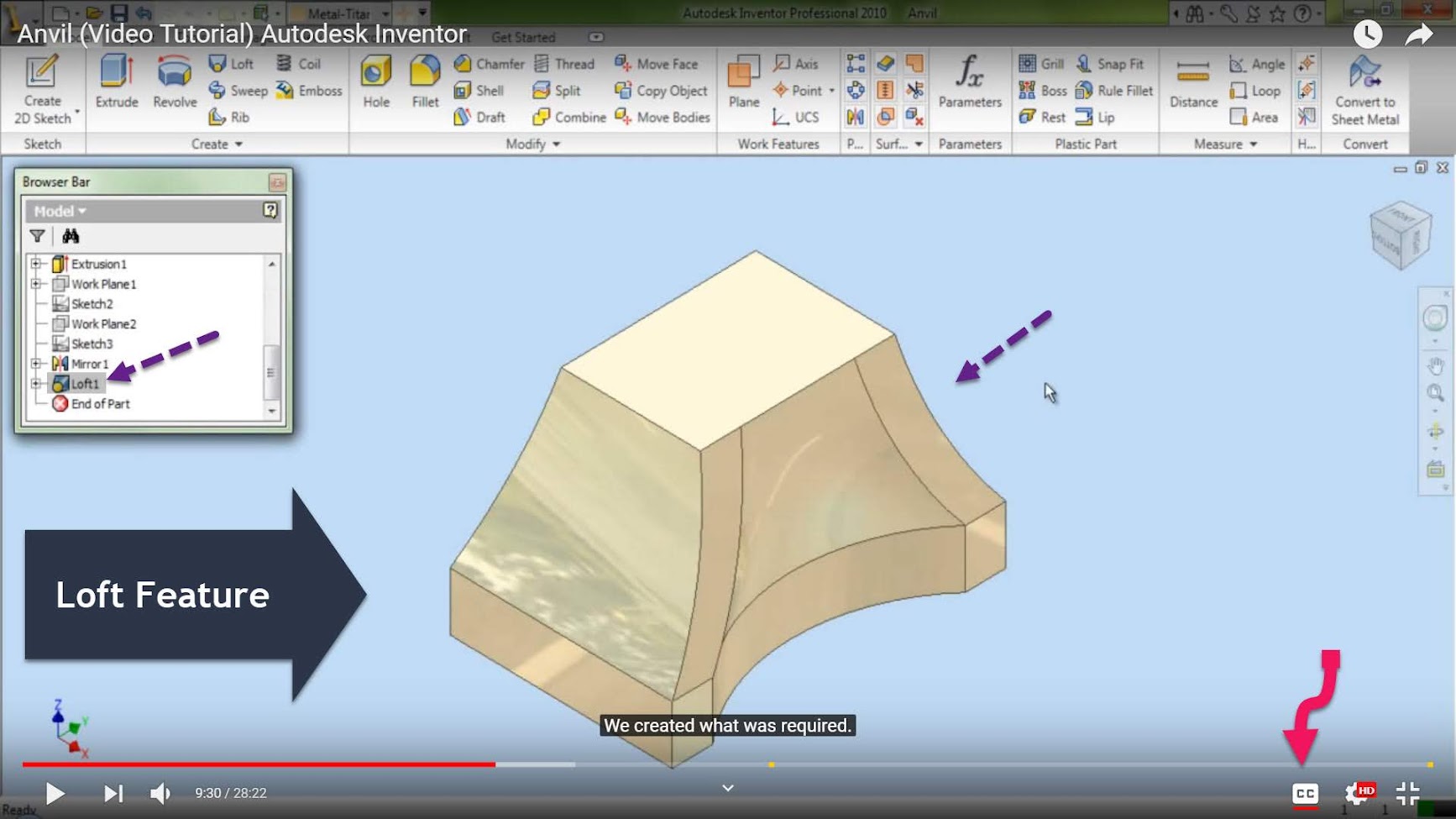
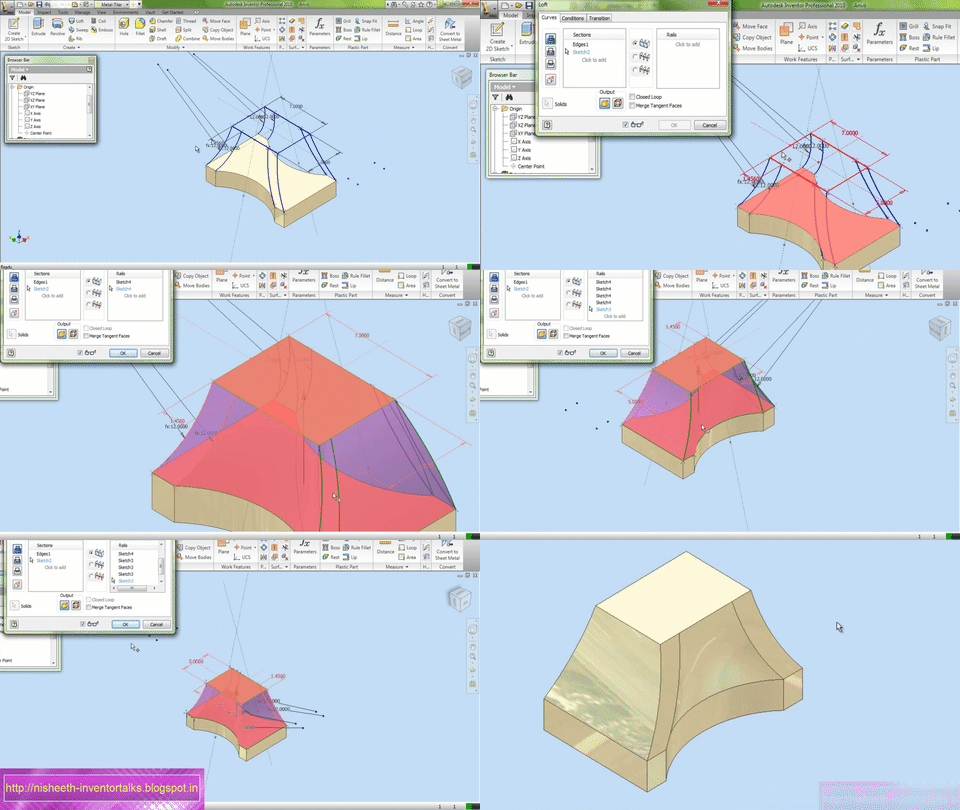
     In this Autodesk Inventor tutorial, we will observe as well as learn the application of Loft Tool. This feature is used, when we want to create a solid by joining more than one closed profile. The rails and points are also used in creating the loft feature that helps in controlling the final outcome.
For creating the loft feature first we will create a profile, then 8 rails. I doing so we will take the help of various 2D sketch features, user defined work planes and Mirror Tool of the software.

Video:--


This loft feature example is taken from our tutorial related to the modelling of Anvil where more complex loft features have been used.


Related Blog Post


…………………………………………………………

Another Loft Tutorial:--


Please check out some more works by us on Autodesk Inventor below--  

Basic tutorials on Autodesk Inventor by us:—(YouTube Playlist of more than 15 videos.)


Detailed tutorials on Autodesk Inventor by us:—(YouTube Playlist of more than 150 videos.)


Hope all of you enjoyed the tutorial. If you find the video useful please like it and share it with your friends/colleagues and do not forget to Subscribe us to get latest updates about our new uploads.

Click to Subscribe us on YouTube

Dear Viewers if you like our work and wanted to support us, to keep continuing the good work, then become a patron of ours at ‘Patreon’ site. Patreon is a simple way for you to contribute to the creator’s work every month/ every time they release their new work and get rewards in return. Please visit the following link to know all about our work and what we are offering as a reward to our patrons…

Friday, December 1, 2017

iTwist Drill -- Autodesk Inventor 2013 Tutorial (with caption and audio narration)

iTwist Drill


Serial No. 288

iTwist Drill -- Autodesk Inventor 2013 Tutorial (with caption and audio narration)

In this part modelling tutorial of ‘Autodesk Inventor,’ we will create a model named ‘iTwist Drill ’. We will start our work by defining some User Parameters that will be used to create a mathematical relation between the dimensions applied in the due course of modelling the ‘Twist Drill’.
Then we will create a circle and extrude it. Next, we will create some user-defined work planes at specified spots. These planes will be used to draw some more sketches, to be used as a base profile for cutting flute (rounded grove) over the round bar. Then a coil feature and an extrude feature with a cut operation will be applied to create flute. Then using a circular pattern tool we will duplicate the same at an angle of 180°. Next, we will create some sketch profiles to cut lip and lip relief on the edge of the drill bit. The process will be the same as applied earlier. Later more coil feature will be applied to complete the model.
The highlight of the videos is the after creating the model with full parameters the iPart creation of the model is also displayed.
Watch the video to understand all the process clearly
.................................................................
To more understand the creation process of an iParts in Autodesk Inventor watch a related video at the following link:---
https://youtu.be/KNCrDJdPm-s.


download-Link


Click the following link to get the model file: - http://bit.ly/2mFTa8o 


Transcription of the Video
  1. Create a new inch part file.
  2. Go to the Manage tab and activate the ‘Parameters’ command.
  3. Add the Parameter name ‘diaMajor’ in the ‘User Parameters’ tab by using 'Add Numeric' key and set the value 7/16 ul in the equation area.
  4. In the same manner, add two more parameters and click OK.
  5. Create a new sketch over XY Plane.
  6. Create a circle and place the dimension, select the ‘List Parameters’ and choose diaMajor and click OK.
  7. Right-click the dimension and select ‘Expression’.
  8. Finish the sketch and activate the ‘Extrude’ command.
  9. The sketch profile will automatically select and set the distance value relating in terms of parameters, click OK.
  10. Save the file as ‘iTwist Drill’.
  11. Change the colour of the model as you wish.
  12. Activate the ‘Plane’ command and create a plane inside from this face.
  13. And place the dimension.
  14. Change the name of the plane as ‘ShankEnd’ and create an Axis in the centre of the part, name it as majorAxis.
  15. Activate the Axis command and select WorkPlane1 and XZ plane.
  16. A new axis will form on the intersection of these two planes.
  17. Change the name of this axis, call it as ‘Intersection Helix Origin Planes’.
  18. Now activate the ‘Point’ command and create a work point at the intersection of this vertical plane and axis .
  19. Activate the ‘Parameters’ command and add HelixAngle in the ‘User Parameters’ tab with the help of ‘Add Numeric’ button.
  20. Now see, different kinds of measurement options are visible here, you choose only one option at a time as per your design.
  21. In the Unit Type dialogue box, select degree option and click OK.
  22. Set the Helix angle to 30 degrees and click OK.
  23. Activate the ‘Plane’ command and select ‘Intersection Helix Origin Planes’ axis and XZ Plane, set the specified angle relating to parameters.
  24. Change the name of this plane, as ‘helix Origin Plane1’.
  25. Close the visibility of ‘ShankEnd’ plane and ‘Intersection Helix Origin Planes’ axis.
  26. Add two more parameters name as ‘web’ and ‘diacutter’.
  27. Create a new sketch on this plane.
  28. Rotate the model parallel to the inclined plane by using ‘Look at Plane’ command.
  29. Activate the slice graphics command.
  30. Take the project of ‘Intersection Helix Origin Planes’ and ‘Work Point1’ with the help of ‘Project Geometry’ command.
  31. Create a circle and set the desired dimensions to fully constrain the sketch.
  32. Finish the sketch and change the name of the sketch as ‘diacutter’.
  33. Add one more parameter call it as ‘helixPitch’.
  34. Activate the ‘Coil’ tool, it will automatically select the sketch profile, select the major axis and select the ‘Cut’ option in the Coil dialogue box.
  35. Go to the Coil Size tab and select the ‘Pitch and Height’ option.
  36. In the Pitch area select from the List Parameters click ‘HelixPitch’ and in the Height area select from the List Parameters, click ‘fluteLen+diaMajor’.
  37. Click OK to create the coil feature.
  38. Open the visibility of ‘diacutter1’ sketch.
  39. Activate the ‘Extrude’ command, select the ‘All’ option in the Extents field and choose ‘Cut’ option and click OK.
  40. Change the name of this extruded cut feature as ‘blend’.
  41. Activate the ‘Circular Pattern’ tool and select the Coil1 and blend feature from the browser bar, select the major axis as a rotation axis and fill the value of Occurrence count and angle.
  42. Click OK to execute the command.
  43. Create a new sketch on this face.
  44. Take the project of these four curves and circle.
  45. Draw a circle and tangent it to this curve.
  46. Select all the sketches and convert it construction geometry.
  47. Create two points on the intersection point of this circle and curve.
  48. Draw a line passing through the centre of the circle and add coincident constraint between line and point.
  49. Take the project of ‘Intersection Helix Origin Planes’ axis.
  50. Set the angular dimension between these two lines.
  51. Finish the sketch and change the name of the sketch as ‘TipRef1’.
  52. Make a Work Axis on this line.
  53. Change the name of the axis as ‘lipReliefGeom’.
  54. Activate the ‘WorkPlane’ command and select these two axes.
  55. Change the name of the plane as ‘lipReliefGeom’.
  56. Now the plane is created along the axis.
  57. Activate the ‘Angle to Plane around Edge’ command.
  58. Select the ‘lipReliefGeom’ plane and ‘majorAxis’, set the angle 90 degrees, click OK.
  59. Add the parameter ‘tipangle’ and set the angle 118 degrees.
  60. Create a new sketch over the ‘lipReliefGeom’ plane.
  61. Activate slice graphics command, take the project of this edge and major axis.
  62. Draw a vertical line and add coincident constraint between the midpoint of a line and centre line.
  63. Draw a horizontal line and join it to the midpoint of the projected line.
  64. In the same manner, draw another line on the opposite side of the sketch and add the equal constraint between these two horizontal lines.
  65. Add the Symmetric constraint between these two lines.
  66. Set the dimensions relating to the parameters on all the sketches.
  67. Finish the sketch and activate the ‘Extrude’ command.
  68. Select the sketch profile, click ‘Cut’ option and select ‘Symmetric’ option, select ‘Through all’ option and Click OK.
  69. Change the name of Extrusion as ‘ptangle’.
  70. Add the parameters ‘lip relief angle’ and ‘lip clearance angle’ and finally set the angle values.
  71. Activate the ‘WorkPlane’ command, select this face and edge and set the value 90-degree, click OK.
  72. In the same way, create another work plane in opposite side of the previous plane, the two workplanes has been created along the taper face.
  73. Change the name of workplane as ‘liprelief’.
  74. Create a new sketch over the ‘lipRelief’plane.
  75. Activate the ‘Look at plane’ command and select the ‘lip relief’ plane for rotating the model along the plane.
  76. Activate the slice graphics command, take the project of ‘major axis’ and ‘lipReliefGeom’ axis.
  77. Draw a circle over the intersection point of vertical and horizontal lines.
  78. Set the dimension, select ‘diaMajor’ from list parameters.
  79. Select all the sketch and convert it to construction geometry.
  80. Draw a horizontal line and a vertical line.
  81. Draw another line from the endpoint of a vertical line passing through center line and connect to the opposite side of the circle.
  82. Apply the angular dimension, select ‘lipClearanceAngle’ from list parameters.
  83. Apply another angular dimension, select ‘lipReliefAngle’ from list parameters.
  84. Create a line from the endpoint of horizontal line and connect to the opposite side of the circle.
  85. Finish the sketch and activate the ‘Extrude’ command.
  86. Choose the ‘Cut’ option → select ‘Symmetric’ option → select ‘All’ option in the Extents field and click OK.
  87. Change the name of Extrusion Cut as ‘liprelief’.
  88. Activate the ‘Circular Pattern’ tool and select the liprelief cut feature → click ‘Continue’ button for selecting as a rotation axis → set the occurrence count and angle value and Click OK.
  89. Activate the ‘Parameters’ command and add the one more parameter named ‘fluteReliefSetback’.
  90. Set the desired value in terms of equation.
  91. Click Ok.
  92. Create a new sketch over the YZ Plane and activate the slice graphics command.
  93. Take the project of the major axis and shankEnd workplane.
  94. Create a rectangle and apply the preferred dimensions.
  95. Change the name of the sketch as ‘clearanceDia’.
  96. Activate the ‘Coil’ tool → select the major axis → go to the Coil Size tab → select the ‘Pitch and Height’ option.
  97. In the Pitch area select ‘HelixPitch’ from the List Parameters and in the Height area select ‘fluteLen+helixpitch’ from the List Parameters.
  98. Go to the Coil Shape tab, select ‘Cut’ option and click OK.
  99. Open the visibility of ‘clearanceDia’ sketch.
  100. Activate the ‘Coil’ tool once again → choose ‘Cut’ option → select the Coil size tab but this time ‘Pitch and Revolution’ should be selected in ‘Type’ area in place of ‘Pitch and Height’ option → set the pitch value as ‘helixPitch’ and set the revolution value 0.25 and taper angle 3 degrees.
  101. Click the ‘Axis’ button to go in the reverse direction of coil feature.
  102. Click OK to create coil feature.
  103. Replicate the pattern of these two coil feature twice times with the help of ‘Circular Pattern’ tool.
  104. Activate the ‘Create iPart’ command.
  105. Remove all the key except ‘diamajor’, ‘oal’, ‘fluteLen’ parameters in the ‘ipart Author’ dialogue box.
  106. Insert new row for creating a new member of different size.
  107. Change the value of diamajor, oal and fluteLen column.
  108. Click Verify button to apply the new member.
  109. Click OK.
  110. Go to the browser bar, under the Table, Let watch here, two row has been created.
  111. The first row is default size and the second row is our new size.
  112. Select each one by one to activate it and observe the result.
  113. Activate the ‘Edit via Excel Spreadsheet’ command.
  114. In the same manner, several members have been created with different sizes in the excel sheet.
  115. We showed some examples of different sizes.
  116. Save the excel file and close it.
  117. Let see here it automatically updates all the family members, which had been added in the browser bar.
  118. Select each one by one to activate it and observe the result.
  119. Save the part file.

Sunday, March 5, 2017

Autodesk Inventor Sheet Metal Tutorial || Project Flat Pattern Command

YouTube-Text-Thumbnail-Temp

This tutorial demonstrates the utilization the Project Flat Pattern Command available in the Sheet Metal modeling environment of Autodesk Inventor. The tool is used to project a selected face or faces of a sheet metal flat pattern onto the active sketch plane.

..............................................................................

Transcription of Video

................................................................................

  1. Here we have a model named Mounting Bracket which is created using Autodesk Inventor’s Sheet Metal functionality. Its two legs have been created using Contour Flange and Face Tool. Now we want to create its third leg by using Face Tool and Fold Tool. Let us see how we will use Project Flat Pattern command in creating third leg.
  2. First of all we need unfolded length of previous leg this can be achieved by using Project Flat Pattern command available in 2D sketching environment.
  3. This is our unfolded projected sketch with the help of this we will create another sketch for the third leg.
  4. On the basis of this sketch we will create an extruded sheet metal face using Face Tool.
  5. Now we need to bend this newly created flat sheet using bend tool.
  6. Again we will utilize the sketch that we got using Project to Flat Pattern Tool to draw new bend lines.
  7. These are the bend lines of previously created leg on basis this we will create our new bend lines.
  8. So now we can easily create our required third leg by folding the visible sheet.
  9. Fully completed model will look like this.

...................................................

Visit the following link to watch full detailed video related to modeling of the Mounting Bracket part

https://www.youtube.com/watch?v=ICPhfxpV9Xg

...................................................

To watch more tutorials related to Autodesk inventor’s sheet metal functionality visit the following link…

https://www.youtube.com/playlist?list=PLKWX3xUP3pPrzu8lASNE9Ol3n7nxlJLG1

..........................................................................................

Hope all of you enjoyed the tutorial. If you find the video useful please like it and share it with your friends/colleagues and do not forget to subscribe us to get latest updates about our new uploads.

http://www.youtube.com/user/nisheethsorjm?sub_confirmation=1

Saturday, February 18, 2017

Chuck and Key || Autodesk Inventor Tutorial

Chuck and Key
In this Autodesk Inventor Tutorial we will create a Chuck and Key Assembly. First we will create Chuck and Key parts and then assemble it. So viewers will learn following Part and Assembly Modelling topics:--
Part Modelling
1. Creating new model file.
2. Basic Sketching
3. Extrude Tool
4. Revolve Tool
5. Sweep Tool
6. Extend Surface
7. Trim Surface
8. Stitch Surface
9. Circular Pattern Tool
10. Combine Tool
11. Hole Tool
Assembly Modelling
1. Creating new assembly file with specified units.
2. Adding components in assembly.
3. Applying Assembly Constraints to properly position parts.


download-Link 

Visit the following link to get the model file…
http://bit.ly/2JC2wdu


...................................................
Visit the following link to watch basic tutorial on Autodesk Inventor by us
https://www.youtube.com/playlist?list=PLb-IhKRMYSERYpB48aY-sZ10fN6CfXIL4
.........................................................................
To watch detailed tutorials on the same software visit the following link
https://www.youtube.com/playlist?list=PL74BDF7431ED13443
..........................................................................................
Hope all of you will enjoyed the tutorial. If you find the video useful please like it and share it with your friends/colleagues and do not forget to subscribe us to get latest updates about our new uploads.
http://www.youtube.com/user/nisheethsorjm?sub_confirmation=1


Saturday, May 28, 2016

Peeler (Autodesk Inventor 2016 Tutorial

Peeler_1

Peeler_2

Serial No. 70

Peeler (Autodesk Inventor 2016 Tutorial)

In this video we will describe, how to modelling ‘Peeler’ with the help of Extrude feature with Surface option, Loft with surface option, Boundary Patch, Mirror, and Rectangular Pattern feature and so on, after creating the surfaces convert all the surfaces into solid body by using ‘Sculpt’ tool. Use Copy Object and Combine command to subtract the one part to another part in assembly environment. How to use Mirror component tool in assembly environment.

download-Link 

Click the following link to get the model file: - http://bit.ly/2njCL9w

Friday, March 18, 2016

Ball Valve || Autodesk Inventor Tutorial

Ball Valve (Thumbnail)

In this Autodesk Inventor tutorial we will create a model named ‘Ball Valve’. Its internal components are created up to a moderate level.

This tutorial will give intermediate level user a good practice of Extrude Tool along with Revolve Tool, Fillet Tool, Chamfer Tool, Thread Tool and 2D sketching on different planes.

download-Link


Visit the following link to get the model file…
http://bit.ly/327oJ9O

Thursday, March 17, 2016

Autodesk Inventor Frame Generator Tutorial || Ladder

Ladder

In this Autodesk Inventor tutorial we will learn about Frame Generator functionality of the software which is available under Design Accelerator section.

First a base sketch will be created which will be used as Frame Reference then later a frame of 50x10 mm size will be used for creating the Ladder.


download-Link


Visit the following link to get the model file…
http://bit.ly/2CaiQOl


.....................................
Video concept courtesy book 'Mastering Autodesk Inventor' by  Curtis Waguespack.

Saturday, October 31, 2015

Piston of Suspension (Autodesk Inventor 2016 Tutorial)

Piston

Serial No. 274

Piston of Suspension  (Autodesk Inventor 2016 Tutorial)

The Design of the model ‘Piston of Suspension’ has been taken from Assembly file of 'Suspension' → ‘Sample files’ → Autodesk Inventor.


download-Link


Click the following link to get the model file: -http://bit.ly/2niHU1X

Suspension_Spring (Autodesk Inventor 2016 Tutorial)

Suspension_Spring

Serial No. 273

Suspension_Spring  (Autodesk Inventor 2016 Tutorial)

The Design of the model ‘Suspension_Spring’ has been taken from Assembly file of 'Suspension' → ‘Sample files’ → Autodesk Inventor.

download-Link


Click the following link to get the model file: -http://bit.ly/2mtD0yD

Friday, October 30, 2015

Rear Hub Bearing (Autodesk Inventor 2016 Tutorial)

Rear Hub Bearing

Serial No. 272

Rear Hub Bearing  (Autodesk Inventor 2016 Tutorial)

The Design of the model ‘Rear Hub Bearing’ has been taken from Assembly file of 'Suspension' → ‘Sample files’ → Autodesk Inventor.


download-Link


Click the following link to get the model file: -http://bit.ly/2niRxO8

Shock Bushing (Autodesk Inventor 2016 Tutorial)

Shock Bushing

Serial No. 271

Shock Bushing  (Autodesk Inventor 2016 Tutorial)

The Design of the model ‘Shock Bushing’ has been taken from Assembly file of 'Suspension' → ‘Sample files’ → Autodesk Inventor.


download-Link


Click the following link to get the model file: -http://bit.ly/2oRRLMN

Shock Cartridge (Autodesk Inventor 2016 Tutorial)

Shock Cartridge.jpg_1

Shock Cartridge.jpg_2

Serial No. 270

Shock Cartridge (Autodesk Inventor 2016 Tutorial)

The Design of the model ‘Shock Cartridge’ has been taken from Assembly file of 'Suspension' → ‘Sample files’ → Autodesk Inventor.


download-Link


Click the following link to get the model file: -http://bit.ly/2mtQpqu

Tuesday, October 27, 2015

Front Shock Brace (Autodesk Inventor 2016 Tutorial)

Front Shock Brace_1

Front Shock Brace_2

Serial No. 269

Front Shock Brace  (Autodesk Inventor 2016 Tutorial)

The Design of the model ‘Front Shock Brace’ has been taken from Assembly file of 'Suspension' → ‘Sample files’ → Autodesk Inventor.


download-Link


Click the following link to get the model file: -http://bit.ly/2o8iKTy

Pillow Ball Retainer (Autodesk Inventor 2016 Tutorial)

Pillow Ball Retainer

Serial No. 268

Pillow Ball Retainer  (Autodesk Inventor 2016 Tutorial)

The Design of the model ‘Pillow Ball Retainer’ has been taken from Assembly file of 'Suspension' → ‘Sample files’ → Autodesk Inventor.


download-Link


Click the following link to get the model file: -http://bit.ly/2ni5vja

Monday, October 26, 2015

Front Upper Arm Mount (Autodesk Inventor 2016 Tutorial)

Front Upper Arm Mount_1Front Upper Arm Mount_2

Serial No. 267

Front Upper Arm Mount  (Autodesk Inventor 2016 Tutorial)

The Design of the model ‘Front Upper Arm Mount’ has been taken from Assembly file of 'Suspension' → ‘Sample files’ → Autodesk Inventor.

In this Inventor Tutorial we will describe how to build the model of ‘Front Upper Arm Mount’. It is a part modelling tutorial, it will cover the following topics.

  • Creating 2D Sketches on different Planes of the model.
  • Use the sketch constraints that are applied on during sketch creation.
  • Use feature commands such as Extrude, Rectangular Pattern, Rib and the Fillet tool.
  • Use Rectangular Pattern tool to create multiple instances of one feature.


download-Link


Click the following link to get the model file: -http://bit.ly/2o2jPMQ