Showing posts with label Drawing Sheet. Show all posts

Thursday, March 2, 2023

Basic Part Modelling_Ex.1 (Autodesk Inventor 2018 Tutorial)


2


1


Serial No. 339.

Dear Viewers, In this video we will create the part and afterward will generate the drawing sheet of this part, If you want to download the part file or drawing sheet file please visit our blog.

This video will cover the following Topics

• 2D Sketching on YZ, XZ & XY Planes. • Different kinds of Extrude command operations like Join, Cut, Distance, Through All, From & To options.

  • Fillet Tool.

• How to create a simple hole over the part by using the Holt Tool command.

• About the Rib Tool.

How to generate the drawing sheet of this part in this software?

• Place the Base and Projected views of this part in the inventor drawing sheet file.

• Apply the dimension over the views by using the Dimension Tool.

• How to modify the dimension styles & increase the font size of the dimensions under the ‘Style & Standard Editor” in the software.

Hope all of you enjoyed the tutorial.


Click the following link to get the model file: - http://bit.ly/3SGwYW2


....................................................................................................
Visit the following link to watch the basic tutorial on Autodesk Inventor by us
https://www.youtube.com/playlist?list=PLb-IhKRMYSERYpB48aY-sZ10fN6CfXIL4
.........................................................................
To watch detailed tutorials on the same software visit the following link
https://www.youtube.com/playlist?list=PL74BDF7431ED13443
..........................................................................................
Hope all of you enjoyed the tutorial. If you find the video useful please like it and share it with your friends/colleagues and do not forget to subscribe us to get latest updates about our new uploads.
http://www.youtube.com/user/niveshandnisheeth?sub_confirmation=1
....................................................................................................
Dear Viewers if you like our work and wanted to support us, to keep continuing the good work, then become a patron of ours at ‘Patreon’ site. Patreon is a simple way for you to contribute to the creator’s work every month/ every time they release their new work and get rewards in return. Please visit the following link to know all about our work and what we are offering as the reward to our patrons…
https://www.patreon.com/nisheethsri+

Monday, March 30, 2015

Autodesk Inventor Basic Tutorial || Sheet Metal

Cover-2

(Tutorial Concept Curtsy – Default SolidWorks Software Help)

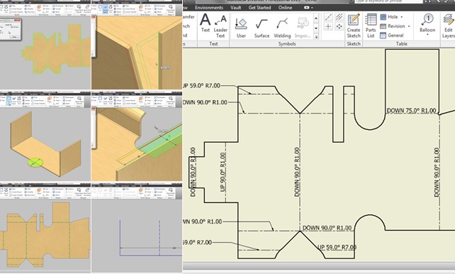
In this tutorial we will learn about the basic techniques related to Autodesk Inventor’s Sheet Metal functionality by modelling a Cover.

In creation process of this model we will start our work by creating some basic sketches utilising the constrains and dimensions.

After defining the Sheet Metal Defaults we will use Contour Flange, Cut, Mirror, Face Tool, Fold/Unfold, Flanges at different angle and Corner Seam Tool to complete the model.

Later we will generate the Flat Pattern of the model and examine the Extents of sheet along with Bend Order Annotation.

In the end we will create Drawing Sheet of the model where we will place Folded as well as Flat Pattern of the model along with Bend Notes.

Addition to this after successfully completing the tutorial, all of you can watch more videos on Sheet Metal by us to practice more and learn more…

Recommended Playlist of Sheet Metal Videos by us….

https://www.youtube.com/playlist?list=PLKWX3xUP3pPrzu8lASNE9Ol3n7nxlJLG1

Note:--
We have given sufficient amount of pause over the tool tip and command prompt in the video, so that they can be read easily…must focus on them to learn and understand the software in detail.

download-Link


Click the following link to get the model file: - http://bit.ly/33hkOII


Video Screen Shots

Thursday, July 24, 2014

Creating Detail View (Autodesk Inventor 2013)

Creating Detail View

Video Tutorial with caption

download-Link


Click the following link to get the model file: - http://bit.ly/2Ch3zvc


Transcription of Video

  1. Open the Hopper Flange (.ipt) part file.
  2. Create a new Drawing sheet with metric template.
  3. Activate the Base View command from the marking menu.
  4. Notice that when the part file is already opened, here model file is automatically displayed in the File drop-down.
  5. View Orientation of the Base View should be (Top) and set the view scale to (0.6).
  6. Click the left mouse button at the upper side of the sheet. Then move your cursor downward of the base view followed by clicking the left mouse button.
  7. Click Create button from the context menu to generate the views.
  8. Save the file with the name Hopper Flange.
  9. Activate the ‘Detail View’ tool from the Create Panel and select the View1 to define it as the parent view.
  10. Detail View dialog box is visible in the graphics window.
  11. In the ‘Fence Shape’ field, there are two option first Circular and the second Rectangular for the detail view.
  12. The Circular shape is selected by default.
  13. Set View Scale 1.5 and click inside of this slot to define the center point of the fence.
  14. Drag the fence as displayed and click the right side of the sheet to place the detail view.

Creating a Section View (Autodesk Inventor 2013)

Creating a Section View

This tutorial displays how to create a Section View in the Drawing Sheet.

download-Link


Click the following link to get the model file: - http://bit.ly/2JT9ICc


Transcription of Video

  1. Create a new Drawing sheet with metric template.
  2. Activate the Base View command from the marking menu.
  3. Open the Housing Fixture (.ipt) part file.
  4. Set the View Scale of the base view 3:1 from the drop down list.
  5. Click the toggle visibility button.
  6. Enter the text FRONT VIEW in the ‘View Identifier’ field.
  7. Click OK to place the view.
  8. Save the drawing sheet with the name Housing Fixture.
  9. Activate Section View from the Create Panel and select the Base View to define it as the parent view.
  10. Hover the mouse pointer over parent view to find the dotted inference line which defines the Center of the Base View and click to start creating section line.
  11. Click Continue button from the right click context menu, Section View dialogue box appears. From here View identifier name and scale can be edited.
  12. Click in the design window to place the section view.
  13. Save the file.

Creating Base View and Projected View (Autodesk Inventor 2013)

Creating Base View and Projected View in Drawing Sheet

This video tutorial displays how to create Base View and the Projected View along with View name and Scale label in a Drawing Sheet.


download-Link


  Click the following link to get the model file: - http://bit.ly/2JUuyRL 


Transcription of Video

  1. Here a blank drawing sheet is open, using the ANSI (mm).idw template.
  2. Right click in the graphics window and activate the ‘Base View’ command.
  3. Drawing View dialog box is visible in the design window.
  4. Click the ‘Open an existing file’ icon.
  5. Open the Mount Bracket.ipt file.
  6. In the Orientation field, there are different types of pre-defined view orientations that can be placed in the drawing page.
  7. Front view is selected by default.
  8. By default the view scale is 1:1 of the model which can be changed from here.
  9. If you hover the mouse over the drawing sheet, a preview of the Mount Bracket will be visible with the front view in the design window.
  10. Click the left mouse button at the bottom of the page. Then move your cursor upward and left side from the base view followed by clicking the left mouse button.
  11. At last, move the cursor on the upper right corner of the design window for placing the isometric view.
  12. Right click in the graphics window and click Create button in the context menu to generate the desired views.
  13. Save the drawing sheet with the name Mount Bracket.
  14. Double click the Base view to edit it.
  15. Click the ‘Toggle Label Visibility’ icon to show the View name and Scale label on the drawing sheet.
  16. Click OK to close the dialog box.
  17. In the same way edit the three other projected views.

Starting a New Drawing Sheet (Autodesk Inventor 2013)

Starting a New Drawing Sheet

Video Tutorial with caption


Transcription of Video

  1. On the Quick Access toolbar, click the New icon.
  2. In the Create New File dialogue box, there are two types of pre-defined templates, one is English (inch) and the other is Metric (mm), from where Part, Assembly, Drawing and Presentation file can be created.
  3. In the Metric template, select the ANSI (mm).idw file.
  4. Click Create button to open the new drawing sheet.
  5. New Drawing sheet will be opened in the design window.