Showing posts with label Contour Flange. Show all posts

Saturday, March 11, 2017

Mounting Bracket || Solid Edge Sheet Metal Tutorial

Mounting Bracket (1280x720)


This tutorial displays the modelling process of a model named 'Mounting Bracket' which is created by using Sheet Metal functionality of Solid Edge software.

The tutorial will give an intermediate level user of the software a good practice of following software tools:--

  1. Tab
  2. Contour Flange
  3. Cutout
  4. Bend
  5. Flange
  6. Break corner
  7. Hole
  8. Pattern

The highlight of the tutorial is that we will apply different tools to create similar looking four legs of the model. Viewers may find this way of modelling process a bit tedious but it is deliberately done so that software users may know and learn about the application of different software tools.

To understand the video easily, focus over places where we have paused our mouse. This is done so as the viewers can easily read the tooltips generated by the software and understand what is being done and why.


download-Link


Visit the following link to get the model file…

http://bit.ly/2N28Zk8


...................................................

Visit the following link to watch more tutorial on Solid Edge by us

https://www.youtube.com/playlist?list=PLKWX3xUP3pPq5ijHdni6jXNX445Il3MWJ

..........................................................................................

Hope all of you will enjoyed the tutorial. If you find the video useful please like it and share it with your friends/colleagues and do not forget to subscribe us to get latest updates about our new uploads.

http://www.youtube.com/user/nisheethsorjm?sub_confirmation=1

Monday, March 30, 2015

Autodesk Inventor Basic Tutorial || Sheet Metal

Cover-2

(Tutorial Concept Curtsy – Default SolidWorks Software Help)

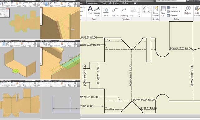
In this tutorial we will learn about the basic techniques related to Autodesk Inventor’s Sheet Metal functionality by modelling a Cover.

In creation process of this model we will start our work by creating some basic sketches utilising the constrains and dimensions.

After defining the Sheet Metal Defaults we will use Contour Flange, Cut, Mirror, Face Tool, Fold/Unfold, Flanges at different angle and Corner Seam Tool to complete the model.

Later we will generate the Flat Pattern of the model and examine the Extents of sheet along with Bend Order Annotation.

In the end we will create Drawing Sheet of the model where we will place Folded as well as Flat Pattern of the model along with Bend Notes.

Addition to this after successfully completing the tutorial, all of you can watch more videos on Sheet Metal by us to practice more and learn more…

Recommended Playlist of Sheet Metal Videos by us….

https://www.youtube.com/playlist?list=PLKWX3xUP3pPrzu8lASNE9Ol3n7nxlJLG1

Note:--
We have given sufficient amount of pause over the tool tip and command prompt in the video, so that they can be read easily…must focus on them to learn and understand the software in detail.

download-Link


Click the following link to get the model file: - http://bit.ly/33hkOII


Video Screen Shots

Tuesday, January 28, 2014

Application of ‘Contour Flange’ & ‘Contour Roll’ tool-Autodesk Inventor 2013 (with caption and audio)

Application of 'Contour Flange' and 'Contour Roll' tool

Serial No. 199

Application of ‘Contour Flange’ & ‘Contour Roll’ tool-Autodesk Inventor 2013 (with caption and audio)


Transcription of Video

  1. This is the model of Square Bend Tube that is created by us earlier. A full-fledged video related to this can be found on our You Tube Channel.

  2. Here from the Browser Bar you can check the history of its modelling. Contour Flange and Contour Roll were used to create this model.

  3. In this video we will describe about the aforesaid features and show how they work.

      Contour Flange Feature

      1. Contour Flange tool is available on Create panel of Sheet Metal Tab.

      2. Contour Flange is used when you have created an open sketch profile with the help of lines, arcs, splines or elliptical arcs etc. and you want to create a flange on basis of it.

      3. When you want to create a flange on basis of a sketch profile created with the help of lines, arcs, splines or elliptical arcs etc. then Contour Flange is used.

      4. The most important requirement for this tool is an open sketch profile; you cannot use this tool with a closed sketch profile.

          Contour Flange applied in the modelling of Square Bend Tube (First instance)

          1. This is the open sketch profile that is used for flange creation.

          2. After activating the Contour Flange Tool, select the sketch profile that is visible in the graphics window.

          3. Distance is automatically set as Width Extents Type.

          4. Distance value 200 mm is filled already.

          5. From here you can flip the extent direction.

          6. Click OK to create the Contour Flange feature.

              Contour Flange applied in the modelling of Square Bend Tube (Second instance)

              1. This time the visible projected edge of the model will be used to create sheet metal flange.

              2. Activate the tool and select the visible sketch having the projected edges of the model.

              3. Expand the more button to find additional option of Contour Flange dialogue box.

              4. Set the Width Extents Type to Distance.

              5. Fill the distance value 200 mm.

              6. Click OK to create the Contour Flange feature.

                  Contour Roll Feature

                  1. Contour Roll Feature is used to revolve an open sketch profile around an axis to develop a sheet metal flange.

                  2. This tool is available on the Create panel of Sheet Metal Tab.

                      Contour Roll applied in the modelling of Square Bend Tube (First instance)

                      1. This is the open sketch profile consisting projected model edges and an axis.

                      2. After activating the Contour Roll Tool, select the sketch profile visible in the graphics window.

                      3. Now Axis selection is active so select the axis for revolution.

                      4. Fill 30 degree in Rolled Angle input box.

                      5. Click OK to close the Contour Roll dialogue box.

                          Contour Roll applied in the modelling of Square Bend Tube (Second instance)

                          1. This time the visible projected edge of the model will be used to create sheet metal flange.

                          2. Activate the Contour Roll Tool and follow the same procedure, as applied earlier to create the Contour Roll feature.

                          3. The final result is visible in the design window.

                          Sunday, October 20, 2013

                          Mounting Bracket (Autodesk Inventor 2012)

                          Mounting Bracket

                          Serial No. 177

                          Mounting Bracket (Autodesk Inventor 2012)


                          The model ‘Mounting Bracket’ has been picked up from ‘Sample files’ of Autodesk Inventor 2012.
                          This video displays the it’s modelling process. This part is created by using Sheet Metal features of Autodesk Inventor.
                          First of all, the base will be created using face tool, afterward similar looking four legs of the part will be created using various tools (Contour Flange, Face with a double bend, Fold and Flange). Usage of Project Flat Pattern is also displayed.

                          download-Link 

                          Click the following link to get the model file: - http://bit.ly/2nIqNGs