Showing posts with label Autodesk Inventor 2013. Show all posts

Friday, December 1, 2017

iTwist Drill -- Autodesk Inventor 2013 Tutorial (with caption and audio narration)

iTwist Drill


Serial No. 288

iTwist Drill -- Autodesk Inventor 2013 Tutorial (with caption and audio narration)

In this part modelling tutorial of ‘Autodesk Inventor,’ we will create a model named ‘iTwist Drill ’. We will start our work by defining some User Parameters that will be used to create a mathematical relation between the dimensions applied in the due course of modelling the ‘Twist Drill’.
Then we will create a circle and extrude it. Next, we will create some user-defined work planes at specified spots. These planes will be used to draw some more sketches, to be used as a base profile for cutting flute (rounded grove) over the round bar. Then a coil feature and an extrude feature with a cut operation will be applied to create flute. Then using a circular pattern tool we will duplicate the same at an angle of 180°. Next, we will create some sketch profiles to cut lip and lip relief on the edge of the drill bit. The process will be the same as applied earlier. Later more coil feature will be applied to complete the model.
The highlight of the videos is the after creating the model with full parameters the iPart creation of the model is also displayed.
Watch the video to understand all the process clearly
.................................................................
To more understand the creation process of an iParts in Autodesk Inventor watch a related video at the following link:---
https://youtu.be/KNCrDJdPm-s.


download-Link


Click the following link to get the model file: - http://bit.ly/2mFTa8o 


Transcription of the Video
  1. Create a new inch part file.
  2. Go to the Manage tab and activate the ‘Parameters’ command.
  3. Add the Parameter name ‘diaMajor’ in the ‘User Parameters’ tab by using 'Add Numeric' key and set the value 7/16 ul in the equation area.
  4. In the same manner, add two more parameters and click OK.
  5. Create a new sketch over XY Plane.
  6. Create a circle and place the dimension, select the ‘List Parameters’ and choose diaMajor and click OK.
  7. Right-click the dimension and select ‘Expression’.
  8. Finish the sketch and activate the ‘Extrude’ command.
  9. The sketch profile will automatically select and set the distance value relating in terms of parameters, click OK.
  10. Save the file as ‘iTwist Drill’.
  11. Change the colour of the model as you wish.
  12. Activate the ‘Plane’ command and create a plane inside from this face.
  13. And place the dimension.
  14. Change the name of the plane as ‘ShankEnd’ and create an Axis in the centre of the part, name it as majorAxis.
  15. Activate the Axis command and select WorkPlane1 and XZ plane.
  16. A new axis will form on the intersection of these two planes.
  17. Change the name of this axis, call it as ‘Intersection Helix Origin Planes’.
  18. Now activate the ‘Point’ command and create a work point at the intersection of this vertical plane and axis .
  19. Activate the ‘Parameters’ command and add HelixAngle in the ‘User Parameters’ tab with the help of ‘Add Numeric’ button.
  20. Now see, different kinds of measurement options are visible here, you choose only one option at a time as per your design.
  21. In the Unit Type dialogue box, select degree option and click OK.
  22. Set the Helix angle to 30 degrees and click OK.
  23. Activate the ‘Plane’ command and select ‘Intersection Helix Origin Planes’ axis and XZ Plane, set the specified angle relating to parameters.
  24. Change the name of this plane, as ‘helix Origin Plane1’.
  25. Close the visibility of ‘ShankEnd’ plane and ‘Intersection Helix Origin Planes’ axis.
  26. Add two more parameters name as ‘web’ and ‘diacutter’.
  27. Create a new sketch on this plane.
  28. Rotate the model parallel to the inclined plane by using ‘Look at Plane’ command.
  29. Activate the slice graphics command.
  30. Take the project of ‘Intersection Helix Origin Planes’ and ‘Work Point1’ with the help of ‘Project Geometry’ command.
  31. Create a circle and set the desired dimensions to fully constrain the sketch.
  32. Finish the sketch and change the name of the sketch as ‘diacutter’.
  33. Add one more parameter call it as ‘helixPitch’.
  34. Activate the ‘Coil’ tool, it will automatically select the sketch profile, select the major axis and select the ‘Cut’ option in the Coil dialogue box.
  35. Go to the Coil Size tab and select the ‘Pitch and Height’ option.
  36. In the Pitch area select from the List Parameters click ‘HelixPitch’ and in the Height area select from the List Parameters, click ‘fluteLen+diaMajor’.
  37. Click OK to create the coil feature.
  38. Open the visibility of ‘diacutter1’ sketch.
  39. Activate the ‘Extrude’ command, select the ‘All’ option in the Extents field and choose ‘Cut’ option and click OK.
  40. Change the name of this extruded cut feature as ‘blend’.
  41. Activate the ‘Circular Pattern’ tool and select the Coil1 and blend feature from the browser bar, select the major axis as a rotation axis and fill the value of Occurrence count and angle.
  42. Click OK to execute the command.
  43. Create a new sketch on this face.
  44. Take the project of these four curves and circle.
  45. Draw a circle and tangent it to this curve.
  46. Select all the sketches and convert it construction geometry.
  47. Create two points on the intersection point of this circle and curve.
  48. Draw a line passing through the centre of the circle and add coincident constraint between line and point.
  49. Take the project of ‘Intersection Helix Origin Planes’ axis.
  50. Set the angular dimension between these two lines.
  51. Finish the sketch and change the name of the sketch as ‘TipRef1’.
  52. Make a Work Axis on this line.
  53. Change the name of the axis as ‘lipReliefGeom’.
  54. Activate the ‘WorkPlane’ command and select these two axes.
  55. Change the name of the plane as ‘lipReliefGeom’.
  56. Now the plane is created along the axis.
  57. Activate the ‘Angle to Plane around Edge’ command.
  58. Select the ‘lipReliefGeom’ plane and ‘majorAxis’, set the angle 90 degrees, click OK.
  59. Add the parameter ‘tipangle’ and set the angle 118 degrees.
  60. Create a new sketch over the ‘lipReliefGeom’ plane.
  61. Activate slice graphics command, take the project of this edge and major axis.
  62. Draw a vertical line and add coincident constraint between the midpoint of a line and centre line.
  63. Draw a horizontal line and join it to the midpoint of the projected line.
  64. In the same manner, draw another line on the opposite side of the sketch and add the equal constraint between these two horizontal lines.
  65. Add the Symmetric constraint between these two lines.
  66. Set the dimensions relating to the parameters on all the sketches.
  67. Finish the sketch and activate the ‘Extrude’ command.
  68. Select the sketch profile, click ‘Cut’ option and select ‘Symmetric’ option, select ‘Through all’ option and Click OK.
  69. Change the name of Extrusion as ‘ptangle’.
  70. Add the parameters ‘lip relief angle’ and ‘lip clearance angle’ and finally set the angle values.
  71. Activate the ‘WorkPlane’ command, select this face and edge and set the value 90-degree, click OK.
  72. In the same way, create another work plane in opposite side of the previous plane, the two workplanes has been created along the taper face.
  73. Change the name of workplane as ‘liprelief’.
  74. Create a new sketch over the ‘lipRelief’plane.
  75. Activate the ‘Look at plane’ command and select the ‘lip relief’ plane for rotating the model along the plane.
  76. Activate the slice graphics command, take the project of ‘major axis’ and ‘lipReliefGeom’ axis.
  77. Draw a circle over the intersection point of vertical and horizontal lines.
  78. Set the dimension, select ‘diaMajor’ from list parameters.
  79. Select all the sketch and convert it to construction geometry.
  80. Draw a horizontal line and a vertical line.
  81. Draw another line from the endpoint of a vertical line passing through center line and connect to the opposite side of the circle.
  82. Apply the angular dimension, select ‘lipClearanceAngle’ from list parameters.
  83. Apply another angular dimension, select ‘lipReliefAngle’ from list parameters.
  84. Create a line from the endpoint of horizontal line and connect to the opposite side of the circle.
  85. Finish the sketch and activate the ‘Extrude’ command.
  86. Choose the ‘Cut’ option → select ‘Symmetric’ option → select ‘All’ option in the Extents field and click OK.
  87. Change the name of Extrusion Cut as ‘liprelief’.
  88. Activate the ‘Circular Pattern’ tool and select the liprelief cut feature → click ‘Continue’ button for selecting as a rotation axis → set the occurrence count and angle value and Click OK.
  89. Activate the ‘Parameters’ command and add the one more parameter named ‘fluteReliefSetback’.
  90. Set the desired value in terms of equation.
  91. Click Ok.
  92. Create a new sketch over the YZ Plane and activate the slice graphics command.
  93. Take the project of the major axis and shankEnd workplane.
  94. Create a rectangle and apply the preferred dimensions.
  95. Change the name of the sketch as ‘clearanceDia’.
  96. Activate the ‘Coil’ tool → select the major axis → go to the Coil Size tab → select the ‘Pitch and Height’ option.
  97. In the Pitch area select ‘HelixPitch’ from the List Parameters and in the Height area select ‘fluteLen+helixpitch’ from the List Parameters.
  98. Go to the Coil Shape tab, select ‘Cut’ option and click OK.
  99. Open the visibility of ‘clearanceDia’ sketch.
  100. Activate the ‘Coil’ tool once again → choose ‘Cut’ option → select the Coil size tab but this time ‘Pitch and Revolution’ should be selected in ‘Type’ area in place of ‘Pitch and Height’ option → set the pitch value as ‘helixPitch’ and set the revolution value 0.25 and taper angle 3 degrees.
  101. Click the ‘Axis’ button to go in the reverse direction of coil feature.
  102. Click OK to create coil feature.
  103. Replicate the pattern of these two coil feature twice times with the help of ‘Circular Pattern’ tool.
  104. Activate the ‘Create iPart’ command.
  105. Remove all the key except ‘diamajor’, ‘oal’, ‘fluteLen’ parameters in the ‘ipart Author’ dialogue box.
  106. Insert new row for creating a new member of different size.
  107. Change the value of diamajor, oal and fluteLen column.
  108. Click Verify button to apply the new member.
  109. Click OK.
  110. Go to the browser bar, under the Table, Let watch here, two row has been created.
  111. The first row is default size and the second row is our new size.
  112. Select each one by one to activate it and observe the result.
  113. Activate the ‘Edit via Excel Spreadsheet’ command.
  114. In the same manner, several members have been created with different sizes in the excel sheet.
  115. We showed some examples of different sizes.
  116. Save the excel file and close it.
  117. Let see here it automatically updates all the family members, which had been added in the browser bar.
  118. Select each one by one to activate it and observe the result.
  119. Save the part file.

Friday, August 21, 2015

Thursday, August 6, 2015

Autodesk Inventor Basic Tutorial || Coil and Sweep

Spring

In this tutorial, we will learn about the Coil and Sweep Feature of Autodesk Inventor by creating a ‘Spring’.  
Coil Tool is used to creating helical coil spring or thread feature. In this tutorial, we will see how springs can be created by using it.
Sweep Feature is used when we want to create a solid using a closed sketch profile and a path.
Addition to this, the creation process of the Helical Curve and Circular Pattern Tool is also displayed in the video. 


Note:—
The video does not have audio assistance but we have given sufficient amount of pause over the tool tip and command prompt so that they can be read easily…must focus on them to learn and understand the software in detail.

download-Link 

Click the following link to get the model file: -http://bit.ly/33gbq8c

Thursday, May 14, 2015

Autodesk Inventor Basic Tutorial || Revolve and Pattern

mhousing_1

(Tutorial Concept Curtsy – Default SolidWorks Software Help)

In this tutorial we would learn about the Revolve and Pattern Feature of Autodesk Inventor by developing a solid named ‘mhousing’. In creation process of this model we will start our work by creating some basic sketches utilising the sketch constrains and dimensions then use Revolve feature to develop a 3D solid. Later we will use an Extrude Feature and a Shell Feature to proceed ahead. Again a sketch profile will be created to apply an Extruded Cut operation to remove some material from the solid. Now we will use a Rectangular Pattern Tool and a Circular Pattern Tool to duplicate the cavity formed by our last Extruded Cut operation and to complete the model.

And after successfully completing the tutorial, all of you can watch more similar tutorials by us, to practice more and learn more…

Recommended Playlist of similar Videos by us….

https://www.youtube.com/playlist?list=PLb-IhKRMYSERYpB48aY-sZ10fN6CfXIL4

Note:--

We have given sufficient amount of pause over the tool tip and command prompt so that they can be read easily…must focus on them to learn and understand the software in detail.

Video Screen Shots


download-Link


Click the following link to get the model file: -http://bit.ly/2oNweF5

Friday, April 17, 2015

Pipe Fittings (Autodesk Inventor 2013)


Serial No. 31
Pipe Fittings (Autodesk Inventor 2013)

We have added the audio on this video so that you can understand it this video more easily. Inside this Autodesk Inventor tutorial, viewers can watch the full detailed process of creating pipe fitting components which are 3-D Parametric CAD Models. In this video, we will demonstrate how to modelling of Pipe Fittings names such as Nipple, Socket, Elbow, Three-Way Elbow and Tee components. In modelling of this video, we have used NPT Thread sketch profile in the cutting of realistic thread. We have used Coil tool for creating the thread over these components.


download-Link 


Click the following link to get the model file: -http://bit.ly/2lAUt81


....................................................................................................
Visit the following link to watch the basic tutorial on Autodesk Inventor by us
https://www.youtube.com/playlist?list=PLb-IhKRMYSERYpB48aY-sZ10fN6CfXIL4
.........................................................................
To watch detailed tutorials on the same software visit the following link
https://www.youtube.com/playlist?list=PL74BDF7431ED13443
..........................................................................................
Hope all of you enjoyed the tutorial. If you find the video useful please like it and share it with your friends/colleagues and do not forget to subscribe us to get latest updates about our new uploads.
http://www.youtube.com/user/niveshandnisheeth?sub_confirmation=1
....................................................................................................
Dear Viewers if you like our work and wanted to support us, to keep continuing the good work, then become a patron of ours at ‘Patreon’ site. Patreon is a simple way for you to contribute to the creator’s work every month/ every time they release their new work and get rewards in return. Please visit the following link to know all about our work and what we are offering as the reward to our patrons…
https://www.patreon.com/nisheethsri+

Friday, April 10, 2015

Modifying Reflection Environment and Default Lightning Settings || Autodesk Inventor


Display of model with default reflection settings

Display of model after modifying the default settings
Sometimes Reflection effect over the model is very irritating. The following videos show how to change it and how default lightning settings can be modified to get desired effect. 

Process of changing the default settings of reflection in Autodesk Inventor

Process of changing the default lightning settings in Autodesk Inventor
Watch the following video to understand the full process in action...


Video Transcription
.....................................
Here you can see the reflection effect which not seems to be soothing. So it should be changed..
Switch to Tools tab and activate the Application options.
In the Colors settings change the Reflection Environment settings by selecting the Chrome.dds file instead of default ParkingLot.dds file.
So after making some moderate changes in the default lightening settings the look of the model can be adjusted to look cool….

Monday, March 30, 2015

Autodesk Inventor Basic Tutorial || Sheet Metal

Cover-2

(Tutorial Concept Curtsy – Default SolidWorks Software Help)

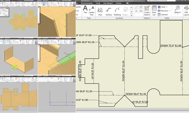
In this tutorial we will learn about the basic techniques related to Autodesk Inventor’s Sheet Metal functionality by modelling a Cover.

In creation process of this model we will start our work by creating some basic sketches utilising the constrains and dimensions.

After defining the Sheet Metal Defaults we will use Contour Flange, Cut, Mirror, Face Tool, Fold/Unfold, Flanges at different angle and Corner Seam Tool to complete the model.

Later we will generate the Flat Pattern of the model and examine the Extents of sheet along with Bend Order Annotation.

In the end we will create Drawing Sheet of the model where we will place Folded as well as Flat Pattern of the model along with Bend Notes.

Addition to this after successfully completing the tutorial, all of you can watch more videos on Sheet Metal by us to practice more and learn more…

Recommended Playlist of Sheet Metal Videos by us….

https://www.youtube.com/playlist?list=PLKWX3xUP3pPrzu8lASNE9Ol3n7nxlJLG1

Note:--
We have given sufficient amount of pause over the tool tip and command prompt in the video, so that they can be read easily…must focus on them to learn and understand the software in detail.

download-Link


Click the following link to get the model file: - http://bit.ly/33hkOII


Video Screen Shots

Sunday, March 22, 2015

Chain-Inventor Studio (Upgraded Design) - Autodesk Inventor 2013

Chain-Inventor Studio (Upgraded Design)

Serial No. 220

Chain-Inventor Studio (Upgraded Design) - Autodesk Inventor 2013

This video displays a setting up of 70 chain links and 3 sprockets along a defined paths in Autodesk Inventor’s  Assembly modelling environment.  First of all some base sketching afterward some advance pattern, adaptive features and assembly mates are to be applied to set up an animation matching the real world scenario… Later the whole mechanism consisting of required mates are driven by using Inventor Studio functionality of the software……


download-Link


Click the following link to get the model file: -http://bit.ly/2nIJIRH

Saturday, March 7, 2015

Autodesk Inventor Basic Tutorial || Link of Chain

Link-Chain

In this tutorial we would learn about the basic techniques of Autodesk inventor by modeling a Link of a chain. In creation process of this model we would learn starting a new part by selecting a specific template, then basic sketching like creating Line, Circles etc. applying sketch constrains and dimensions to create a parametric sketch. Later we would learn about Extrude, Fillet and Mirror tools. Controlling the appearance of the model and lightning setting is also displayed.

We have used this Chain Link in one of our previous animation tutorial which can be found on following link……
https://www.youtube.com/watch?v=Y5mJqJ1fsyc

Note:--
We have given sufficient amount of pause over the tool tip and command prompt in the video, so that they can be read easily…must focus on them to learn and understand the software in detail.

Video Screen Shots


download-Link


Click the following link to get the model file: - http://bit.ly/2PMXYF2

Friday, January 9, 2015

Autodesk Inventor Basic Tutorial - Revolve and Sweep Feature

Candle Stick
(Tutorial Concept Courtesy – Default SolidWorks Software Help)
In this tutorial we would learn about the Revolve and Sweep Feature of Autodesk Inventor by developing a solid named Candle Stick.
Besides this we would also learn how to Extrude with Taper Angle.


download-Link

Click the following link to get the model file: - http://bit.ly/36AXY0Y

Monday, December 22, 2014

Autodesk Inventor Basic Tutorial - Loft Feature

Untitled (Time 0_13_48;23)
In this tutorial we would learn about the Loft feature of Autodesk Inventor by developing a solid named Hammer Head.  This feature is used, when we want to create a solid by joining more than one closed profile. Sometimes optional rails and points are used that help in controlling the final outcome.

Addition to this creation process of new Work Planes, Copy/ Paste function of sketches and many more things are displayed.

download-Link

Click the following link to get the model file: - http://bit.ly/2CcL5Ms


(Tutorial Concept Courtesy – Default SolidWorks Software Help)

Sunday, November 2, 2014

Controlling parameters of assembly by using ‘Derived Component’ (Autodesk Inventor 2013)

Controlling parameters of assembly by using--Derived Component

Serial No. 218

Controlling parameters of assembly by using ‘Derived Component’ (Autodesk Inventor 2013)


  In this video we would create a Hinge. The parts of the Hinge are created on the basis of a derived part. Changing the parameters of derived part, It will change all the parts accordingly in the assembly.  

download-Link


Click the following link to get the model file: - http://bit.ly/2miNXDi

Tuesday, October 21, 2014

Creating Realistic Knurling on the Cylindrical Surface (Autodesk Inventor 2013)

Creating Realistic Knurling on the Cylindrical Surface

Serial No. 217

Creating Realistic Knurling on the Cylindrical Surface (Autodesk Inventor)

This Autodesk Inventor video tutorial demonstrates the way to create a realistic looking knurling on a cylindrical face in Autodesk Inventor.  The model displayed in video is used as a component in the assembly of Pipe Wrench created earlier by us.
The video covers the application of 2D sketching, 3D features like Coil, Circular Pattern, Revolve and Mirror.
Get the file required to complete this tutorial mentioned below.


download-Link


Click the following link to get the model file: - http://bit.ly/2nLcMYM

Monday, June 30, 2014

Create a Wrench as an ‘iPart’ through-Autodesk Inventor 2013 (with caption and audio narration)


Create a Wrench as an 'iPart' through


Serial No. 214

Create a Wrench as an ‘iPart’ through-Autodesk Inventor 2013 (with caption and audio narration)

iParts are different from standard parts they are table driven part factories with a group of parts. The parts have the different parameter and different features that are controlled by table. The table is controlled by iPart Author or Spread Sheet.


  downloadLink13
  

Click the following link to get the model file: - http://bit.ly/2nRnT2d


Transcription of Video

  1. Activate the ‘Create iPart’ command.
  2. iPart Author dialogue box is visible in the graphics window.
  3. Notice that the columns for the named parameters had automatically displayed and iWrench-01 has been added to the current file to define the first family member’s part number.
  4. Discard all named parameters by clicking ‘Remove’ arrow button one by one and again place all these named parameters in desired sequence by using ‘Add’ arrow button.
  5. Click the Other tab button and fill the text in the ‘Name’ field.
  6. ‘Size’ column is automatically added in the table.
  7. Fill the value in size column.
  8. Right click the row of iWrench-01, and click Insert Row in the context menu.
  9. In the second row, change the value in each column for the new member.
  10. Click Verify button.
  11. Click OK to generate the iPart.
  12. Parameter Table has been added in the browser bar.
  13. Click the ‘+’ sign to expand the node.
  14. Right click the iWrench-02 node and choose ‘Activate’ option to change the size of the member.
  15. Activate the first member once again.
  16. Right-click the table icon and select ‘Edit via Spreadsheet’.
  17. The iPart table is opened in Microsoft Excel.
  18. Create another member in the excel file and enter the value in each column.
  19. More parameters can be added with the excel file.
  20. Save the spreadsheet and close it.
  21. Click Yes button to update the table.
  22. In the browser bar, the family members have been automatically added, it can also be seen from the Edit Table.
  23. Click Cancel button to close the dialogue box.

  24. Activate the each family member one by one and see the effect.
  25. Save the ‘iWrench’ file.