Showing posts with label Flat Pattern. Show all posts

Friday, March 24, 2017

Mounting Bracket || SolidWorks Sheet Metal Tutorial

Mounting Bracket (1280x720)

This tutorial displays the modelling process of a model named 'Mounting Bracket' which is created by using Sheet Metal functionality of SolidWorks software.

The tutorial will give an intermediate level user of the software a good practice of following software tools:--

  1. Basic 2D sketching
  2. Base Flange/Tab
  3. Sketched Bend
  4. Edge Flange
  5. Break Corner
  6. Extrude Cut
  7. Simple Hole
  8. Circular Pattern
  9. Mirror
  10. Flat Pattern

The highlight of the tutorial is that we will apply different tools to create similar looking four legs of the model. Viewers may find this way of modelling process a bit tedious but it is deliberately done so that software users may know and learn about the application of different software tools.

To understand the video easily, focus over places where we have paused our mouse. This is done so as the viewers can easily read the tooltips generated by the software and understand what is being done and why.


download-Link


Visit the following link to get the model file…

http://bit.ly/31XO4D4


....................................................................................

Visit the following link to watch more sheet metal tutorials on SolidWorks by us

https://www.youtube.com/playlist?list=PLKWX3xUP3pPrJYXXG2_K2IlquWkPc59lf

....................................................................................

Visit the following link to watch basic tutorial on SolidWorks by us

https://www.youtube.com/playlist?list=PLb-IhKRMYSES3Zw3QHmQVqQ-rcFVzgYHy

.........................................................................

To watch more detailed tutorials on the same software visit the following link

https://www.youtube.com/playlist?list=PLKWX3xUP3pPo77gFCyy669sI76qJa5jKw

...................................................................................

Hope all of you enjoyed the tutorial. If you find the video useful please like it and share it with your friends/colleagues and do not forget to subscribe us to get latest updates about our new uploads.

http://www.youtube.com/user/nisheethsorjm?sub_confirmation=1

....................................................................................................

Thursday, October 13, 2016

Box (mini size) - Video Tutorial (Siemens NX 11)

Box (Mini Size)_1

Box (Mini Size)_2

Serial No. 70.

Box (mini size) - Video Tutorial (Siemens NX 11)

In this Siemens Nx Tutorial we will describe how to build the model of a ‘Box (Mini Size)’ through sheet metal features. It is a part and assembly modeling tutorial, 10 Parts and 3 Assemblies has been created (2 sheet metal parts and 8 other parts) like Box base, Box cover, Wire, Hinge, Sliding and so on in the assembly environment with the help of ‘Create New Component’ command.

It will cover the following topics.

........................................................................................................

• Creating 2D Sketches on different Planes.

• Use the sketch constraints that are applied on during sketch creation.

• Use Sheet metal features such as Tab, Flange, Closed Corner and Flat Pattern.

• Use feature commands such as Extrude, Edge Blend, Mirror feature, Sweep along Guide, Trim body, Unite etc.

• How to set thickness of the sheet and Bend radius by using Sheet Metal Preferences.

• How to create a base feature by extruding a sketch along vector by thickness value by using Tab command.

• How to add a flange at an angle to planar face.

• How to create top-down assembly modelling in Siemens NX software.

• How to remove the degree of freedom of the parts with the help of ‘Assembly Constraints’ command.

• How to rotate the part by using ‘Move Component’ command.

• How to smooth the edges of model by using ‘Visualization Preferences’ command.


download-Link


Click the following link to get the model file: - http://bit.ly/2VqZHk7

Saturday, October 8, 2016

'Stabilizer Cover'-Sheet Metal Modelling-Siemens-NX 11 (Tutorial with Caption)

sheet_metal_model18

Serial No. 69

'Stabilizer Cover'-Sheet Metal Modelling-Siemens-NX 11 (Tutorial with Caption)

The following example shows how to construct the Cover of the Stabilizer with the help of Sheet Metal commands.
____________________________________
This video you will learn:
•    Tab feature
•    Flange Tool
•    Contour Flange
•    Louvers
•    Flat Pattern


download-Link


Click the following link to get the model file: - http://bit.ly/2omwx9M

Friday, August 21, 2015

Creo Parametric Basic Tutorial || Sheet Metal

YouTube Icon-Cover_1

In this tutorial we will learn about the basic techniques related to ‘Sheet Metal’ functionality of ‘Creo Parametric’ by modelling a Cover.
In creation process of this model we will start our work by creating some basic sketches utilising the constrains and dimensions.
Next we will use Extrude Tool to create our first feature and use the same to remove some material form the model. Later we will use Flange Tool and take the help of ‘Mirror Tool’ to duplicate the Extrude Cut and Flange feature to the other side of the sheet. Then we will create another Flange that will also be mirrored to the other side as well. A Flat feature will be added next that will be bend along a line. Moving ahead we will unbend a previously created flange to remove some material form the model and then it would be bend back. Again a Flat feature at an angle of 75° will be created… Now we will create a corner between both the visible walls by using the Extend Tool along with a gap of 0.1 mm. So at the last we will create the Flat Pattern of the model. Next to place the flat pattern and solid model of the part in the drawing sheet we will use Family Table.
Next we will create a drawing file and put the Flat Pattern part in it along with Bend Lines… and export the drawing sheet to a PDF file…


Transcription of Video

  1. Start a new Sheet Metal Part file with the metric template and give it a name ‘Cover’.
  2. Select the Front Datum plane and create a new sketch on this plane.
  3. Draw the sketch using the line tool with the provided dimensions.
  4. Apply constrains time to time to full define the sketch.
  5. The sketch is complete so exit form sketching mode.
  6. Activate the Extrude Tool and specify the thickness of sheet along with extrude length.
  7. Change the material thickness direction and provide the bend radius.
  8. Click green checkmark to execute the command.
  9. Change the colour of the model as per your wish and save your work.
  10. Again activate the Extrude Tool to remove material form the sheet.
  11. This time activate internal sketcher to draw the sketch profile as displayed.
  12. First add some new references to create sketch.
  13. Click green checkmark to execute the command.
  14. Now activate the Flange Tool and select the user defined shape in the profile type option.
  15. Select these edges to specify on which edges new flanges will be created.
  16. Switch to Shape Tab and activate the internal sketcher to draw a shape for the flange.
  17. The sketch is complete so finish it and return back to the flange dialogue box…
  18. Set the Bend Relief type to Rectangular.
  19. Specify the Bend Radius which is by default inside of the thickness.
  20. In the Miter Cut details fill gap and offset values as displayed.
  21. Click green check mark to execute the command.
  22. Select Extrude and Flange Feature from the Model Tree and activate Mirror Tool.
  23. Select Front plane as mirroring plane and click OK.
  24. Now it is asking for new placement edges for the mirrored flanges so define it as shown.
  25. Click green checkmark to execute the command.
  26. Again we will create a new flange on the basis of user defined sketch…
  27. This time we will create the profile of the flange over the front plane.
  28. We do not need the flange, to go through all the way along the edge, so drag these nodes and specify the length from the front plane.
  29. All the other settings should be defined as done in the previous Flange creation.
  30. Now we will mirror this flange to the other side of the wall as done earlier.
  31. Activate the flat the Flat Tool.
  32. Fill the angle for the Flat and define the edge on which the feature is to be created.
  33. Define the length and width of the feature and here also, we do not need the feature to go all along the way, with edge so it should be changed by dragging the node.
  34. Click green check mark to execute the command.
  35. Activate Bend Tool.
  36. First define Bend surface from the Placement Tab.
  37. Draw a bend line by activating an internal sketcher.
  38. Fill the bend angle and side of the bend along with its radius.
  39. Click green check mark to execute the command.
  40. Activate Unbend Tool.
  41. Select Reference type as manual.
  42. Clear the Bend Geometries that are selected automatically and select only one bend.
  43. Click ok to execute the command.
  44. Now activate the Extrude Tool and cut the material from the unbended part.
  45. Ok now we will Bend Back this the flange…..
  46. Next we will create a Flat Feature at an angle of 75°.
  47. Hide the visibility of default Planes.
  48. Activate the Plane Tool and select the following face of the model to create a new plane at an offset distance of 0.1 mm.
  49. Repeat the same steps to create another plane.
  50. Press ALT key on your keyboard and select the following edge of the model.
  51. Activate Extend Tool and select Extend the wall to intersect the reference plane option.
  52. Next specify the reference plane and execute the command.
  53. In the same manner extend the other wall also…
  54. You can see a corner with a gap of 0.1 mm has been created between the two walls.
  55. The preview of flat pattern can be seen at this stage.
  56. Next we will actually create Flat Pattern of the model.
  57. From the Model Tree Setting open Tree Filters.
  58. In Tree Filters Items, turn on the display of Supressed Objects.
  59. From the Model Tree supress the Flat Pattern feature to bring back the folded part in front of us.
  60. Now activate the Family Table tool.
  61. Add the supressed Flat Pattern feature in the Family Table column.
  62. Insert another row where we put unsuppressed Flat Pattern feature which is defined by letter (Y).
  63. Next create a new drawing file.
  64. When select instance dialogue box appears select ‘The generic’ part to place sheet metal general part.
  65. Activate General View command and click anywhere on the screen to place the part.
  66. Orientation of the model is already set to default so now scale the size of model in the drawing sheet.
  67. Set the Display style of the model to Shaded with edges and click ok button.
  68. Unlock view movement and drag the view of the model to upper right part of the sheet.
  69. Press Drawing Models button and select Add Model from the Menu manger to place another instance of the model.
  70. In the Select Instance Dialogue Box click COVER_FLAT instance to place Flat Pattern of the model.
  71. Again repeat the same steps to place the second General View of the model.
  72. Only different setting this time is that we will place the Top view of the model, Display style be No Hidden, Tangent edges will be supressed and scale of the model will be 0.65 percent.
  73. We will remove some unnecessary dimensions.
  74. Click Model Annotations button and place bend lines in the sheet by placing the model datums and notes.
  75. Next we will clean some unnecessary lines and move the Bend Line notes to make it more descriptive.
  76. Our sheet is complete so we will save it and export it to a PDF file.

download-Link


Click the following link to get the model file: -http://bit.ly/2o9dejW

Monday, March 30, 2015

Autodesk Inventor Basic Tutorial || Sheet Metal

Cover-2

(Tutorial Concept Curtsy – Default SolidWorks Software Help)

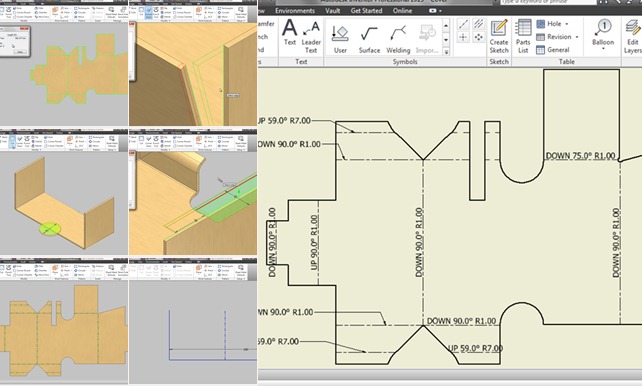
In this tutorial we will learn about the basic techniques related to Autodesk Inventor’s Sheet Metal functionality by modelling a Cover.

In creation process of this model we will start our work by creating some basic sketches utilising the constrains and dimensions.

After defining the Sheet Metal Defaults we will use Contour Flange, Cut, Mirror, Face Tool, Fold/Unfold, Flanges at different angle and Corner Seam Tool to complete the model.

Later we will generate the Flat Pattern of the model and examine the Extents of sheet along with Bend Order Annotation.

In the end we will create Drawing Sheet of the model where we will place Folded as well as Flat Pattern of the model along with Bend Notes.

Addition to this after successfully completing the tutorial, all of you can watch more videos on Sheet Metal by us to practice more and learn more…

Recommended Playlist of Sheet Metal Videos by us….

https://www.youtube.com/playlist?list=PLKWX3xUP3pPrzu8lASNE9Ol3n7nxlJLG1

Note:--
We have given sufficient amount of pause over the tool tip and command prompt in the video, so that they can be read easily…must focus on them to learn and understand the software in detail.

download-Link


Click the following link to get the model file: - http://bit.ly/33hkOII


Video Screen Shots