Showing posts with label Circular Pattern. Show all posts

Friday, March 24, 2017

Mounting Bracket || SolidWorks Sheet Metal Tutorial

Mounting Bracket (1280x720)

This tutorial displays the modelling process of a model named 'Mounting Bracket' which is created by using Sheet Metal functionality of SolidWorks software.

The tutorial will give an intermediate level user of the software a good practice of following software tools:--

  1. Basic 2D sketching
  2. Base Flange/Tab
  3. Sketched Bend
  4. Edge Flange
  5. Break Corner
  6. Extrude Cut
  7. Simple Hole
  8. Circular Pattern
  9. Mirror
  10. Flat Pattern

The highlight of the tutorial is that we will apply different tools to create similar looking four legs of the model. Viewers may find this way of modelling process a bit tedious but it is deliberately done so that software users may know and learn about the application of different software tools.

To understand the video easily, focus over places where we have paused our mouse. This is done so as the viewers can easily read the tooltips generated by the software and understand what is being done and why.


download-Link


Visit the following link to get the model file…

http://bit.ly/31XO4D4


....................................................................................

Visit the following link to watch more sheet metal tutorials on SolidWorks by us

https://www.youtube.com/playlist?list=PLKWX3xUP3pPrJYXXG2_K2IlquWkPc59lf

....................................................................................

Visit the following link to watch basic tutorial on SolidWorks by us

https://www.youtube.com/playlist?list=PLb-IhKRMYSES3Zw3QHmQVqQ-rcFVzgYHy

.........................................................................

To watch more detailed tutorials on the same software visit the following link

https://www.youtube.com/playlist?list=PLKWX3xUP3pPo77gFCyy669sI76qJa5jKw

...................................................................................

Hope all of you enjoyed the tutorial. If you find the video useful please like it and share it with your friends/colleagues and do not forget to subscribe us to get latest updates about our new uploads.

http://www.youtube.com/user/nisheethsorjm?sub_confirmation=1

....................................................................................................

Sunday, March 12, 2017

Creating Realistic Knurling on the Cylindrical Surface (Solid Edge ST9 Tutorial)

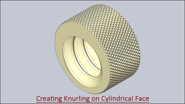
Creating Knurling on Cylindrical Face

Serial No. 41

Creating Realistic Knurling on the Cylindrical Surface (Solid Edge ST9 Tutorial)

This Solid Edge video tutorial demonstrates the way to create a realistic looking knurling on a cylindrical face in Solid Edge ST9.

The model displayed in video is used as a component in the assembly of ‘Pipe Wrench’ created earlier by us.

..........................................................

The modeling process of Pipe wrench which is available in two volumes, can be watched on following link... (1) https://youtu.be/1uIsYZGkqAk, (2) https://youtu.be/baXynQ4jYMg

.........................................................

The video covers the application of 2D sketching, 3D features like Helical Curve command, Swept Cutout command, Circular Pattern, Revolved Cut and Mirror.

Get the file required to complete this tutorial by visiting the following link:--

http://niveshandnisheeth.blogspot.com/2016/11/content-list-videos-solid-edge-st9.html

.......................................................

download-Link


Click the following link to get the model file: - http://bit.ly/2IziFzQ

Sunday, February 12, 2017

Allen Screwdriver—Double Ended (Solid Edge ST9 Tutorial)


Allen Screwdriver (Double Ended)


Serial No. 30


Allen Screwdriver—Double Ended (Solid Edge ST9 Tutorial)
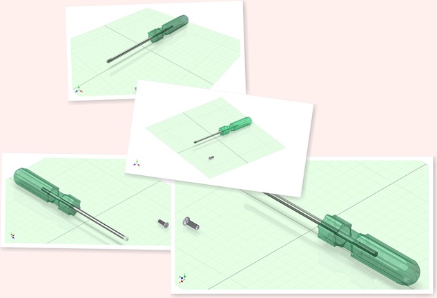
In this Solid Edge Tutorial we will describe how to build the model ‘Allen Screwdriver (Double Ended)’. The edge of Allen screwdriver (Double Ended) has been constructed by different surface tools like Bound, Stitch, Extend etc. It is a Part and Assembly modelling tutorial. This assembly consist 3 part files (Handle, Circular Rod, Sleeve etc.).
It will cover the following topics.
........................................................................................................
• Creating 2D Sketches on different Planes.
• Use some sketch constraints as Connect, Horizontal/Vertical, and Equal etc. that are applied on during sketch creation.
• Use solid and surface feature command such as Revolved Cut, Bounded, Stitched, Extrude, Cut, Circular Pattern, Subtract, Round etc.
• How to create a line by using ‘3D Line’ command in 3D Sketch environment.
• How to change the color of the model by using ‘Part Painter’ tool.
• How to insert component into the assembly using drag and drop from parts library by using ‘Insert Component’ command.
• How to resize (scale) the handle of screwdriver with the help of ‘Part Copy’ command. You use the Part Copy Parameters dialog box to specify which geometry you want to copy and whether you want to mirror, scale, or flatten the copied geometry.
• How to create a sleeve part in context of an assembly in the assembly environment with the help of ‘Create Part In-Place’ command.
• How to mate the parts by using ‘Flash Fit’ command in the assembly.
• How to flip the component by using ‘Flip Side’ option in ‘Flash Fit’ command in the assembly.
• How to lock the rotation of the component by using ‘Lock Rotation’ option in ‘Flash Fit’ command in the assembly.
• Use the ‘Subtract’ command (Boolean) to remove the tool body volume from selected target bodies in the assembly. You can select multiple target bodies and multiple tool bodies.


download-Link

Click the following link to get the model file: - http://bit.ly/35gBCB8


Friday, February 10, 2017

Allen Screwdriver (Solid Edge ST9 Tutorial)


Allen Screwdriver_1

Allen Screwdriver_2

Serial No. 29

Allen Screwdriver (Solid Edge ST9 Tutorial)
In this Solid Edge Tutorial we will describe how to build the model ‘Allen Screwdriver’. The edge of Allen screwdriver has been constructed by different surface tools like Bound, Stitch, Derived etc. It is a Part and Assembly modelling tutorial. This assembly consist 2 part files Screw Driver and Handle that are positioned according to design intent by using Assembly Constraints.
It will cover the following topics.
........................................................................................................
• Creating 2D Sketches on different Planes.
• Use some sketch constraints as Connect, Horizontal/Vertical, and Equal etc. that are applied on during sketch creation.
• Use solid and surface feature command such as Revolved (Surface), Bounded, Stitched, Extrude, Cut, Circular Pattern, Loft, Subtract, Round etc.
• How to patterning an arc and a line by using ‘Derived’ command, this is the easiest way to create a sketch pattern.
• How to create a line by using ‘3D Line’ command in 3D Sketch environment.
• How to create a feature between circle and point by using ‘Loft Protrusion’ command.
• How to change the color of the model by using ‘Part Painter’ tool.
• How to insert component into the assembly using drag and drop from parts library by using ‘Insert Component’ command.
• How to mate the parts by using ‘Flash Fit’ command in the assembly.
• How to lock the rotation of the component by using ‘Lock Rotation’ option in ‘Flash Fit’ command in the assembly.
• Use the ‘Subtract’ command (Boolean) to remove the tool body volume from selected target bodies in the assembly. You can select multiple target bodies and multiple tool bodies.
• How to hide all components except the selected components by using ‘Isolate’ command in the assembly.

download-Link
  
Click the following link to get the model file: - http://bit.ly/2pWfHiu


Wednesday, February 8, 2017

Screw Driver (Solid Edge ST9 Tutorial)

Screw Driver_1

Screw Driver_2

Serial No. 28

Screw Driver (Solid Edge ST9 Tutorial)

In this Solid Edge Tutorial we will describe how to build the model ‘Screw Driver’. The edge of screw driver and handle has been constructed by different surface tools. It is a Part and Assembly modelling tutorial. This assembly consist 2 part files Screw Driver and Handle that are positioned according to design intent by using Assembly Constraints.

It will cover the following topics.

........................................................................................................

• Creating 2D Sketches on different Planes.

• Use some sketch constraints as Connect, Horizontal/Vertical, and Equal etc. that are applied on during sketch creation.

• Use solid and surface feature command such as Revolved (Surface), BlueSurf, Bounded, Stitched, Extrude, Cut, Circular Pattern, Loft, Mirror Copy Feature, Union, Round etc.

• How to change the color of the model by using ‘Part Painter’ tool.

• How to insert component into the assembly using drag and drop from parts library by using ‘Insert Component’ command.

• How to mate the parts by using ‘Flash Fit’ command in the assembly.

• How to lock the rotation of the component by using ‘Lock Rotation’ option in ‘Flash Fit’ command in the assembly.

• How to rotate and moving part by using ‘Drag Component’ command.


download-Link


Click the following link to get the model file: - http://bit.ly/2VnnxgE

Tuesday, April 26, 2016

Creating Realistic Knurling on the Cylindrical Surface (SolidWorks 2014)

Creating Realistic Knurling on the Cylindrical Surface

Serial No. 211

Creating Realistic Knurling on the Cylindrical Surface (SolidWorks)

This SolidWorks video tutorial demonstrates the way to create a realistic looking knurling on a cylindrical face in SolidWorks.
The model displayed in video is used as a component in the assembly of Pipe Wrench created earlier by us.
..........................................................
The modeling process of Pipe wrench which is available in two volumes, can be watched on following link... (1) http://youtu.be/Za-8Maaz1yU, (2) http://youtu.be/bRe2hjJZauw
.........................................................
The video covers the application of 2D sketching, 3D features like Helix/Spiral, Cut-Sweep, Circular Pattern, Cut-Revolve and Mirror.

download-Link


Click the following link to get the model file: - http://bit.ly/3383sxz

Thursday, August 6, 2015

SolidWorks Basic Tutorial || Helical/Spring Curve and Sweep

Spring 1280x720

In this tutorial we will learn about the Helical/Spring Curve and Sweep Feature of SolidWorks by creating a ‘Spring’.

Helical/Spring Curve tool is used to create helical coil spring or thread feature. In this tutorial we will see how springs can be created by using it.

Sweep Feature is used when we want to create a solid using a closed sketch profile and a path.

Addition to this we will also watch how to use Surface Extrude, Projected Curve, and Circular Pattern Tools etc.


Transcription of Video

  1. Create a new part file.
  2. Change units of the file to millimeter, gram, second.
  3. Create a new sketch over front plane.
  4. First create a vertical centerline of infinite length at the origin. This will be used as axis.
  5. Next create a circle in the sketch and position is using the dimension as displayed.
  6. The sketch is complete so exit from the sketching mode.
  7. Switch to feature tab then create a new plane parallel to top plane and at the center point of circle.
  8. Now activate the Helix and Spiral tool.
  9. Now select the newly created plane to draw a circle which will define the helix cross-section.
  10. Draw a circle coincident to the origin of part and previously drawn circle.
  11. Helix and Spiral Tool is active first conform, if the start point of curve is coincident to the origin of profile or not.
  12. The helix start point can be adjusted by controlling the start angle.
  13. We will use Height and Pitch to define the curve.
  14. Fill the height and pitch values as shown.
  15. Change the direction of the curve to Counterclockwise.
  16. Click ok to create the curve.
  17. Activate the sweep tool.
  18. First define the Sweep profile then the path.
  19. Click Ok to execute the command.
  20. Change the colour of the model as per your wish.
  21. Now create a new sketch over right plane.
  22. Use convert entities tool to project the edges of spring and draw the following sketch.
  23. Fully define the sketch by adding dimensions and constrains.
  24. The sketch is complete so exit from the sketching mode.
  25. Again create a new sketch over front plane as displayed.
  26. Switch to surface tab and activate extrude surface tool.
  27. Select the sketched arc and from the direction 1 filed define the Mid Plate option.
  28. Drag this arrow to define the length of extrude.
  29. Click green check mark to create the surface extrude feature.
  30. Next activate projected curve tool.
  31. First define sketch to project then projection face.
  32. Reverse the projection direction and preview will be visible.
  33. Click green check mark to execute the command.
  34. Now create a new sketch over this face and project this edge in the sketch.
  35. Now activate sweep tool and create a sweep feature as displayed.
  36. Now draw a new sketch over right plane to be used as axis.
  37. Activate circular pattern tool.
  38. First define feature to pattern and then the pattern axis.
  39. Fill the angle for the pattern.
  40. Click green check mark to execute the command.
  41. The model is complete so save the file.

download-Link


Click the following link to get the model file: http://bit.ly/32kr4y6

Autodesk Inventor Basic Tutorial || Coil and Sweep

Spring

In this tutorial, we will learn about the Coil and Sweep Feature of Autodesk Inventor by creating a ‘Spring’.  
Coil Tool is used to creating helical coil spring or thread feature. In this tutorial, we will see how springs can be created by using it.
Sweep Feature is used when we want to create a solid using a closed sketch profile and a path.
Addition to this, the creation process of the Helical Curve and Circular Pattern Tool is also displayed in the video. 


Note:—
The video does not have audio assistance but we have given sufficient amount of pause over the tool tip and command prompt so that they can be read easily…must focus on them to learn and understand the software in detail.

download-Link 

Click the following link to get the model file: -http://bit.ly/33gbq8c

Thursday, May 14, 2015

Autodesk Inventor Basic Tutorial || Revolve and Pattern

mhousing_1

(Tutorial Concept Curtsy – Default SolidWorks Software Help)

In this tutorial we would learn about the Revolve and Pattern Feature of Autodesk Inventor by developing a solid named ‘mhousing’. In creation process of this model we will start our work by creating some basic sketches utilising the sketch constrains and dimensions then use Revolve feature to develop a 3D solid. Later we will use an Extrude Feature and a Shell Feature to proceed ahead. Again a sketch profile will be created to apply an Extruded Cut operation to remove some material from the solid. Now we will use a Rectangular Pattern Tool and a Circular Pattern Tool to duplicate the cavity formed by our last Extruded Cut operation and to complete the model.

And after successfully completing the tutorial, all of you can watch more similar tutorials by us, to practice more and learn more…

Recommended Playlist of similar Videos by us….

https://www.youtube.com/playlist?list=PLb-IhKRMYSERYpB48aY-sZ10fN6CfXIL4

Note:--

We have given sufficient amount of pause over the tool tip and command prompt so that they can be read easily…must focus on them to learn and understand the software in detail.

Video Screen Shots


download-Link


Click the following link to get the model file: -http://bit.ly/2oNweF5

Saturday, January 31, 2015

Mesh of Table Fan (SolidWorks 2014 Tutorial)

Mesh of Table Fan_1

Mesh of Table Fan_2

Mesh of Table Fan_3

Serial No. 67

Mesh of Table Fan (SolidWorks 2014 Tutorial)

In this SolidWorks Assembly tutorial we will demonstrate the creation process of the model named ‘Mesh of Table Fan’. The assembly contains three components. First part named Mesh Front and Mesh Rear will be created individually which can be termed Bottom Up designing process. At a glance the Mesh Front and Mesh Rear looks quite same but they are different that is why they are created separately. Later both components will be put into the assembly and positioned by using mates and the third component is created in context of assembly.
In the tutorial viewers will be able to see the Solidworks Basic functions like 2D sketching, dimensioning, application of sketch relations and usage of 3D features like Revolved Boss/Base,Swept Boss/Base, Lofted Boss/Base, Circular Pattern, Boss Extrude and Reference Geometry feature like Dividing points etc.


 download-Link


Click the following link to get the model file: - http://bit.ly/2nZiXJo

Tuesday, October 21, 2014

Creating Realistic Knurling on the Cylindrical Surface (Autodesk Inventor 2013)

Creating Realistic Knurling on the Cylindrical Surface

Serial No. 217

Creating Realistic Knurling on the Cylindrical Surface (Autodesk Inventor)

This Autodesk Inventor video tutorial demonstrates the way to create a realistic looking knurling on a cylindrical face in Autodesk Inventor.  The model displayed in video is used as a component in the assembly of Pipe Wrench created earlier by us.
The video covers the application of 2D sketching, 3D features like Coil, Circular Pattern, Revolve and Mirror.
Get the file required to complete this tutorial mentioned below.


download-Link


Click the following link to get the model file: - http://bit.ly/2nLcMYM

Thursday, September 11, 2014

Building the Pattern Features Sample Part (SolidWorks 2014)

mhousing

Serial No. 8

Building the Pattern Features Sample Part (SolidWorks 2014)


In this Basic Tutorial of SolidWorks we will demonstrate the utilization of part modelling feature named Revolve and Pattern.
Revolve Feature is used when we want to create a solid by revolving a closed sketch profile through a specified angle and along an axis.
Pattern Feature is used when we want to replicate a feature. This can be one or two dimensional array of that feature.
The aforesaid features are utilized quite an often while designing parts. This tutorial is picked up from the default tutorials that comes up with the software. You can find its written version under Basic Techniques → Pattern Features
Following is the description that is mentioned in the original Tutorial..

In this lesson, you learn how to build the sample part used in the Pattern Features tutorial.

The steps include:

  • Creating a revolved base feature
  • Extruding a thin feature
  • Shelling a part

_______________________________________________________________

In this section of lesson, you learn how to create a linear pattern and a circular pattern. A linear pattern is a one- or two-dimensional array of features. A circular pattern is a circular array of features.

The steps include:

  • Creating an oblong cut
  • Creating a linear pattern
  • Creating a circular pattern
  • Using an equation to drive the circular pattern

download-Link


Click the following link to get the model file: - http://bit.ly/2oo3FgO

Sunday, August 3, 2014

Getting Started Tutorial Part-1 (SolidWorks 2014)

Pressure Plate

Serial No. 4

Getting Started Tutorial Part-1 (SolidWorks 2014)

Video Tutorial with Captions

The Design of this model is selected from 'SolidWorks Tutorials':--
Getting Started → Introduction to SolidWorks
The Introduction to SolidWorks lesson guides you through the creation of a part and drawing.
This lesson includes:
Creating base, boss, and cut features from sketches
Adding fillets to smooth edges
Creating a circular pattern
Adding drawing views
Adding centerlines, center marks, and dimensions to the drawing.

download-Link 

   Click the following link to get the model file: - http://bit.ly/2ooDruY

Monday, January 27, 2014

Application of ‘Sweep' tool and ‘Circular Pattern’ tool-Autodesk Inventor 2013 (with caption and audio)

Application of ‘Sweep’ tool and ‘Circular Pattern’ tool

Serial No. 198

Application of ‘Sweep' tool and ‘Circular Pattern’ tool-Autodesk Inventor 2013 (with caption and audio)

In this exercise we will create a new part named ‘Blade-base’, related to our previously created full-fledged model ‘Mixer (Cabinet)’.

In this part file we will utilize following feature/tools: - 2D Sketches, work planes, extrude, fillet, sweep and circular pattern.


download-Link 


Click the following link to get the model file: - http://bit.ly/2nMCMms


Transcription of Video

  1. Create a New Standard (in).ipt file.
  2. Create a new sketch on the XY Plane with the aid of ‘Create 2D Sketch’ tool.
  3. Draw the sketch diagram of part ‘Blade-base’ with the help of line tool.
  4. Pick up the Offset tool and select all lines in the graphics window.
  5. Enter the offset distance 1/16 inch between these two lines.
  6. Close the sketch profile by adding lines where the gap exists.
  7. Now the sketch is complete.
  8. Finish the 2D sketch.
  9. Select any one of the line of enclosed profile, the mini-toolbar will appear in the graphics window.
  10. Click the ‘Create Extrude’ icon.
  11. It will automatically select the enclosed profile.
  12. Extrude dialogue box is visible in the graphics window.
  13. In the Extents field, select ‘Symmetric’ option.
  14. Enter the distance value 3/8 inch.
  15. Click OK to create the extrude feature.
  16. Change the model colour to ‘Steel’.
  17. Save the file with the name ‘Blade-base’.
  18. Activate the Fillet tool from the Modify panel of 3D Model tab.
  19. Fillet dialogue box is visible in the graphics window.
  20. Select four bend edges of the model.
  21. Set the value to 1/16 inch in ‘Radius’ field.
  22. Click OK to create the fillet feature.
  23. Now make some changes in the settings of the software.
  24. Go to the Options panel of Tools tab and click Application Options icon.
  25. Application Options dialogue box is visible in the graphics window.
  26. General tab is active by default.
  27. Switch to Sketch tab.
  28. Click on the Standard Toggle box of 'Autoproject edges for sketch creation and edit' option.
  29. Apply and close the dialogue box.
  30. Create a new sketch on the blue face of the model, it will be used as a profile for the sweep.
  31. Select the projected model edges in the graphics window and convert them into construction geometry.
  32. Draw a line from Point1 of length 1/8 inch, parallel to Z direction of prevailing 3D indicator in the graphics window.
  33. Draw another line from the same Point1 of length 3/64 inch, parallel to Y direction.
  34. Close the profile by adding a new line.
  35. Finish the 2D Sketch.
  36. On the Ribbon click ‘Plane’ icon on the Work Features panel of 3D Model tab.
  37. Click on Point2 and select corresponding edge of the model (indicated by red colour).
  38. Work Plane has been created, perpendicular to this edge.
  39. Create a new sketch on this Work Plane to create a path for sweep.
  40. Right click in the graphics window and choose ‘Slice Graphics’ option.
  41. Take the project of the model by using ‘Project Cut Edges’ tool.
  42. Convert the entire projected model edges into construction geometry except yellow coloured line and arc.
  43. Add a new line starting from Point3 of length 0.75833 inch over the projected model edge indicated by yellow colour.
  44. Finish the 2D Sketch.
  45. Activate the ‘Sweep’ tool from Create panel of 3D Model tab.
  46. Sweep dialogue box is visible in the graphics window.
  47. Since there is only one closed profile, the profile drawn on Sketch2 is selected automatically.
  48. The Path selection button is active in the Sweep dialogue box.
  49. Select the sketch profile drawn on Sketch3 as sweep path in the graphics window.
  50. Select ‘Cut’ option to remove the material.
  51. Click OK to execute the Sweep feature.
  52. On the Ribbon click ‘Circular Pattern’ icon on the Pattern panel of 3D Model tab.
  53. Circular Pattern dialogue box is visible in the graphics window.
  54. In the Circular Pattern dialogue box, ‘Features’ selection button is activated by default.
  55. Select the ‘Sweep1’ in the Browser Bar as feature to pattern.
  56. Right click in the graphics window and choose Continue from the context menu.
  57. Select the Y Axis in the Browser Bar to define axis of revolution.
  58. Set the pattern count value 2 in the ‘Placement’ field.
  59. Leave the pattern angle 360 degree unchanged which is set by default.
  60. Click OK to execute the Circular Pattern feature.
  61. Create a new sketch on the blue face of ‘Blade-base’.
  62. Draw a square of length ¾ inch with the aid of ‘Three Point Centre Rectangle’ tool, coincident with autoprojected part origin.
  63. Activate the ‘Three Point Centre Rectangle’ from the Draw panel of Sketch tab.
  64. Click on Point4 to set the center point of the rectangle.
  65. Right click in the graphics window and click OK to finish the rectangle command.
  66. Exit the sketching environment.
  67. Activate the Extrude command from the marking menu.
  68. And select the square.
  69. In the Extents field, select ‘To’ option from the drop down list.
  70. Select back face of the model and choose Join option.
  71. Click OK to create Extrude feature.
  72. Create a new sketch once again on the blue face of model.
  73. Draw another square of length 3/16 inch.
  74. Use this square to remove material from the model by using Extrude tool.

Thursday, May 16, 2013

Allen Screwdriver

This is the rendering images of our previously created model Allen Screwdriver.

Watch the following video to understand the modelling process of tip of the Allen Screwdriver.

By watching the video the viewer will be able to understand the application of following features / tolls of Autodesk Inventor.
 

Creating Work Planes

Creating Work Planes_1

  Creating Work Planes_2 Creating Work Planes_3
  Creating Work Planes_4
Project Cut Edges
(With converting it into construction line)
Project Cut Edges_1
  Project Cut Edges_2
Circular Pattern Circular Pattern_1
  Circular Pattern_2

Loft Feature

Loft Feature_1
  Loft Feature_2
Placing Component in Assembly Placing Component in Assembly_1
  Placing Component in Assembly_2
  Placing Component in Assembly_3
Rotating Component in an Assembly Rotating Component in an Assembly_1
Assembly Constrains (Mate) Assembly Constrains_1
  Assembly Constraints_2
  Assembly Constraints_3
  Assembly Constraints_4
Copy Object Copy Object_1
Sculpt(Remove Material) Sculpt(Remove option)_1
Interference Analysis Interference Analysis_1

I recommend that viewers should get the finished Part/Assembly associated with the video to easily understand the video. Visit the following link  to get the part file---

Allen Screwdriver (Autodesk Inventor 2010)