Showing posts with label Screw. Show all posts

Monday, February 17, 2020

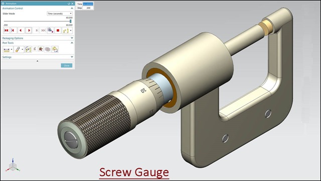
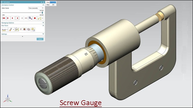
Screw Gauge Modelling with Motion Simulation (Volume-1) Solid Edge ST 9 Tutorial

Serial No. 110-A

Screw Gauge Modelling with Motion Simulation (Volume-1) Solid Edge ST 9 Tutorial

(Rest of the model is designed in Volume-2 & 3)

Dear Viewers, in this video we will show how to build the 'Screw Gauge' assembly in Solid Edge ST9 Software. This model contains two Subassemblies first Frame subassembly and second Thimble subassembly. Eleven-part files like Frame1, Anvil, Barrel1, Thimble, Plate1, Stem1, Washer, Spindle, Screw etc. will be used to build this model. Hope you will enjoy this tutorial. At the end of this video, we will display how to simulate this model by giving the 'Screw' & 'Cylindrical' joints in a motion analysis environment. Please subscribe to our channel to get the latest updates and share this video their friends and colleagues.


Click the following link to get the model file: - http://bit.ly/38GHcOE


Procedure of reading of Screw Gauge

Total number of divisions imprinted on Circular scale (in one round) = 25

Total number of divisions imprinted on Linear scale = 40

Pitch of Linear scale = total length of Linear scale/total number of divisions imprinted on Linear scale
= 25.4mm/40 = 0.635mm

Least count of Circular scale = Pitch of Linear scale/total number of divisions imprinted on Circular scale
= 0.635mm/25 = 0.0254mm

Reading of Linear scale = Pitch of Linear scale x Number of divisions opened on Linear scale
= 0.635mm x 4 = 2.54mm

Reading of Circular scale = Least count of Circular scale x Number of divisions
ahead of central line of Linear scale
= 0.0254mm x 2 = 0.0508mm

Total Reading = Reading of Linear scale + Reading of Circular scale
= 2.54mm + 0.0508mm = 2.5908mm

.................................................………………………………….
Visit the following link to watch more tutorial on Solid Edge by us
https://www.youtube.com/playlist?list=PLKWX3xUP3pPq5ijHdni6jXNX445Il3MWJ
..........................................................................................
Hope all of you enjoyed the tutorial. If you find the video useful please like it and share it with your friends/colleagues and do not forget to subscribe us to get latest updates about our new uploads.
http://www.youtube.com/user/nisheethsorjm?sub_confirmation=1m
....................................................................................................
Dear Viewers if you like our work and wanted to support us, to keep continuing the good work, then become a patron of ours at ‘Patreon’ site. Patreon is a simple way for you to contribute to the creator’s work every month/ every time they release their new work and get rewards in return. Please visit the following link to know all about our work and what we are offering a reward to our patrons…
https://www.patreon.com/nisheethsri

Screw Gauge Modelling with Motion Simulation (Volume-2) Solid Edge ST 9 Tutorial

Serial No. 110-B

Screw Gauge Modelling with Motion Simulation (Volume-2) Solid Edge ST 9 Tutorial

(Rest of the model is designed in Volume-1 & 3)

Dear Viewers, in this video we will show how to build the 'Screw Gauge' assembly in Solid Edge ST9 Software. This model contains two Subassemblies first Frame subassembly and second Thimble subassembly. Eleven-part files like Frame1, Anvil, Barrel1, Thimble, Plate1, Stem1, Washer, Spindle, Screw etc. will be used to build this model. Hope you will enjoy this tutorial. At the end of this video, we will display how to simulate this model by giving the 'Screw' & 'Cylindrical' joints in a motion analysis environment. Please subscribe to our channel to get the latest updates and share this video their friends and colleagues.


Click the following link to get the model file: - http://bit.ly/38GHcOE


Procedure of reading of Screw Gauge

Total number of divisions imprinted on Circular scale (in one round) = 25

Total number of divisions imprinted on Linear scale = 40

Pitch of Linear scale = total length of Linear scale/total number of divisions imprinted on Linear scale
= 25.4mm/40 = 0.635mm

Least count of Circular scale = Pitch of Linear scale/total number of divisions imprinted on Circular scale
= 0.635mm/25 = 0.0254mm

Reading of Linear scale = Pitch of Linear scale x Number of divisions opened on Linear scale
= 0.635mm x 4 = 2.54mm

Reading of Circular scale = Least count of Circular scale x Number of divisions
ahead of central line of Linear scale
= 0.0254mm x 2 = 0.0508mm

Total Reading = Reading of Linear scale + Reading of Circular scale
= 2.54mm + 0.0508mm = 2.5908mm

.................................................………………………………….
Visit the following link to watch more tutorial on Solid Edge by us
https://www.youtube.com/playlist?list=PLKWX3xUP3pPq5ijHdni6jXNX445Il3MWJ
..........................................................................................
Hope all of you enjoyed the tutorial. If you find the video useful please like it and share it with your friends/colleagues and do not forget to subscribe us to get latest updates about our new uploads.
http://www.youtube.com/user/nisheethsorjm?sub_confirmation=1m
....................................................................................................
Dear Viewers if you like our work and wanted to support us, to keep continuing the good work, then become a patron of ours at ‘Patreon’ site. Patreon is a simple way for you to contribute to the creator’s work every month/ every time they release their new work and get rewards in return. Please visit the following link to know all about our work and what we are offering a reward to our patrons…
https://www.patreon.com/nisheethsri

Screw Gauge Modelling with Motion Simulation (Volume-3) Solid Edge ST 9 Tutorial

Serial No. 110-C

Screw Gauge Modelling with Motion Simulation (Volume-3) Solid Edge ST 9 Tutorial

(Rest of the model is designed in Volume-1 & 2)

Dear Viewers, in this video we will show how to build the 'Screw Gauge' assembly in Solid Edge ST9 Software. This model contains two Subassemblies first Frame subassembly and second Thimble subassembly. Eleven-part files like Frame1, Anvil, Barrel1, Thimble, Plate1, Stem1, Washer, Spindle, Screw etc. will be used to build this model. Hope you will enjoy this tutorial. At the end of this video, we will display how to simulate this model by giving the 'Screw' & 'Cylindrical' joints in a motion analysis environment. Please subscribe to our channel to get the latest updates and share this video their friends and colleagues.


Click the following link to get the model file: - http://bit.ly/38GHcOE


Procedure of reading of Screw Gauge

Total number of divisions imprinted on Circular scale (in one round) = 25

Total number of divisions imprinted on Linear scale = 40

Pitch of Linear scale = total length of Linear scale/total number of divisions imprinted on Linear scale
= 25.4mm/40 = 0.635mm

Least count of Circular scale = Pitch of Linear scale/total number of divisions imprinted on Circular scale
= 0.635mm/25 = 0.0254mm

Reading of Linear scale = Pitch of Linear scale x Number of divisions opened on Linear scale
= 0.635mm x 4 = 2.54mm

Reading of Circular scale = Least count of Circular scale x Number of divisions
ahead of central line of Linear scale
= 0.0254mm x 2 = 0.0508mm

Total Reading = Reading of Linear scale + Reading of Circular scale
= 2.54mm + 0.0508mm = 2.5908mm

.................................................………………………………….
Visit the following link to watch more tutorial on Solid Edge by us
https://www.youtube.com/playlist?list=PLKWX3xUP3pPq5ijHdni6jXNX445Il3MWJ
..........................................................................................
Hope all of you enjoyed the tutorial. If you find the video useful please like it and share it with your friends/colleagues and do not forget to subscribe us to get latest updates about our new uploads.
http://www.youtube.com/user/nisheethsorjm?sub_confirmation=1m
....................................................................................................
Dear Viewers if you like our work and wanted to support us, to keep continuing the good work, then become a patron of ours at ‘Patreon’ site. Patreon is a simple way for you to contribute to the creator’s work every month/ every time they release their new work and get rewards in return. Please visit the following link to know all about our work and what we are offering a reward to our patrons…
https://www.patreon.com/nisheethsri

Screw Gauge Modelling with Animation (Volume-1) SolidWorks 2017 Tutorial

Serial No. 230-A

Screw Gauge Modelling with Animation (Volume-1) SolidWorks 2017 Tutorial

(Rest of the model is designed in Volume-2 & 3)

Dear Viewers, in this video we will show how to build the 'Screw Gauge' assembly in SolidWorks 2017 Software. This model contains two Subassemblies first Frame subassembly and second Thimble subassembly. Eleven-part files like Frame1, Anvil, Barrel1, Thimble, Plate1, Stem1, Washer, Spindle, Screw etc. will be used to build this model. Hope you will enjoy this tutorial. At the end of this video, we will display how to simulate this model in motion study environment by giving the 'Screw' & 'Distance' mate command. Please subscribe to our channel to get the latest updates and share this video their friends and colleagues.


Click the following link to get the model file: - http://bit.ly/2OW8jNC


Procedure of reading of Screw Gauge

Total number of divisions imprinted on Circular scale (in one round) = 25

Total number of divisions imprinted on Linear scale = 40

Pitch of Linear scale = total length of Linear scale/total number of divisions imprinted on Linear scale
= 25.4mm/40 = 0.635mm

Least count of Circular scale = Pitch of Linear scale/total number of divisions imprinted on Circular scale
= 0.635mm/25 = 0.0254mm

Reading of Linear scale = Pitch of Linear scale x Number of divisions opened on Linear scale
= 0.635mm x 4 = 2.54mm

Reading of Circular scale = Least count of Circular scale x Number of divisions
ahead of central line of Linear scale
= 0.0254mm x 2 = 0.0508mm

Total Reading = Reading of Linear scale + Reading of Circular scale
= 2.54mm + 0.0508mm = 2.5908mm

……………………………………………………………………………………………………………………………………………………

Our motive to upload this video is to show our workability/experience and to share our knowledge with the viewers and learners.
...........................................................................................
Visit the following link to watch the basic tutorial on SolidWorks by us
https://www.youtube.com/playlist?list=PLb-IhKRMYSES3Zw3QHmQVqQ-rcFVzgYHy
.........................................................................
To watch more detailed tutorials on the same software visit the following link
https://www.youtube.com/playlist?list=PLKWX3xUP3pPo77gFCyy669sI76qJa5jKw
...................................................................................
Hope all of you enjoyed the tutorial. If you find the video useful please like it and share it with your friends/colleagues and do not forget to subscribe us to get latest updates about our new uploads.
http://www.youtube.com/user/nisheethsorjm?sub_confirmation=1
....................................................................................................
Dear Viewers if you like our work and wanted to support us, to keep continuing the good work, then become a patron of ours at ‘Patreon’ site. Patreon is a simple way for you to contribute to the creator’s work every month/ every time they release their new work and get rewards in return. Please visit the following link to know all about our work and what we are offering a reward to our patrons…
https://www.patreon.com/nisheethsri

Screw Gauge Modelling with Animation (Volume-2) SolidWorks 2017 Tutorial

Serial No. 230-B

Screw Gauge Modelling with Animation (Volume-2) SolidWorks 2017 Tutorial

(Rest of the model is designed in Volume-1 & 3)

Dear Viewers, in this video we will show how to build the 'Screw Gauge' assembly in SolidWorks 2017 Software. This model contains two Subassemblies first Frame subassembly and second Thimble subassembly. Eleven-part files like Frame1, Anvil, Barrel1, Thimble, Plate1, Stem1, Washer, Spindle, Screw etc. will be used to build this model. Hope you will enjoy this tutorial. At the end of this video, we will display how to simulate this model in motion study environment by giving the 'Screw' & 'Distance' mate command. Please subscribe to our channel to get the latest updates and share this video their friends and colleagues.


Click the following link to get the model file: - http://bit.ly/2OW8jNC


Procedure of reading of Screw Gauge

Total number of divisions imprinted on Circular scale (in one round) = 25

Total number of divisions imprinted on Linear scale = 40

Pitch of Linear scale = total length of Linear scale/total number of divisions imprinted on Linear scale
= 25.4mm/40 = 0.635mm

Least count of Circular scale = Pitch of Linear scale/total number of divisions imprinted on Circular scale
= 0.635mm/25 = 0.0254mm

Reading of Linear scale = Pitch of Linear scale x Number of divisions opened on Linear scale
= 0.635mm x 4 = 2.54mm

Reading of Circular scale = Least count of Circular scale x Number of divisions
ahead of central line of Linear scale
= 0.0254mm x 2 = 0.0508mm

Total Reading = Reading of Linear scale + Reading of Circular scale
= 2.54mm + 0.0508mm = 2.5908mm

………………………………………………………………………………………………………………………………………………………..

Our motive to upload this video is to show our workability/experience and to share our knowledge with the viewers and learners.
...........................................................................................
Visit the following link to watch the basic tutorial on SolidWorks by us
https://www.youtube.com/playlist?list=PLb-IhKRMYSES3Zw3QHmQVqQ-rcFVzgYHy
.........................................................................
To watch more detailed tutorials on the same software visit the following link
https://www.youtube.com/playlist?list=PLKWX3xUP3pPo77gFCyy669sI76qJa5jKw
...................................................................................
Hope all of you enjoyed the tutorial. If you find the video useful please like it and share it with your friends/colleagues and do not forget to subscribe us to get latest updates about our new uploads.
http://www.youtube.com/user/nisheethsorjm?sub_confirmation=1
....................................................................................................
Dear Viewers if you like our work and wanted to support us, to keep continuing the good work, then become a patron of ours at ‘Patreon’ site. Patreon is a simple way for you to contribute to the creator’s work every month/ every time they release their new work and get rewards in return. Please visit the following link to know all about our work and what we are offering a reward to our patrons…
https://www.patreon.com/nisheethsri

Screw Gauge Modelling with Animation (Volume-3) SolidWorks 2017 Tutorial

Serial No. 230-C

Screw Gauge Modelling with Animation (Volume-3) SolidWorks 2017 Tutorial

(Rest of the model is designed in Volume-1 & 2)

Dear Viewers, in this video we will show how to build the 'Screw Gauge' assembly in SolidWorks 2017 Software. This model contains two Subassemblies first Frame subassembly and second Thimble subassembly. Eleven-part files like Frame1, Anvil, Barrel1, Thimble, Plate1, Stem1, Washer, Spindle, Screw etc. will be used to build this model. Hope you will enjoy this tutorial. At the end of this video, we will display how to simulate this model in motion study environment by giving the 'Screw' & 'Distance' mate command. Please subscribe to our channel to get the latest updates and share this video their friends and colleagues.


Click the following link to get the model file: - http://bit.ly/2OW8jNC


Procedure of reading of Screw Gauge

Total number of divisions imprinted on Circular scale (in one round) = 25

Total number of divisions imprinted on Linear scale = 40

Pitch of Linear scale = total length of Linear scale/total number of divisions imprinted on Linear scale
= 25.4mm/40 = 0.635mm

Least count of Circular scale = Pitch of Linear scale/total number of divisions imprinted on Circular scale
= 0.635mm/25 = 0.0254mm

Reading of Linear scale = Pitch of Linear scale x Number of divisions opened on Linear scale
= 0.635mm x 4 = 2.54mm

Reading of Circular scale = Least count of Circular scale x Number of divisions
ahead of central line of Linear scale
= 0.0254mm x 2 = 0.0508mm

Total Reading = Reading of Linear scale + Reading of Circular scale
= 2.54mm + 0.0508mm = 2.5908mm

………………………………………………………………………………………………………………………………………………………..

Our motive to upload this video is to show our workability/experience and to share our knowledge with the viewers and learners.
...........................................................................................
Visit the following link to watch the basic tutorial on SolidWorks by us
https://www.youtube.com/playlist?list=PLb-IhKRMYSES3Zw3QHmQVqQ-rcFVzgYHy
.........................................................................
To watch more detailed tutorials on the same software visit the following link
https://www.youtube.com/playlist?list=PLKWX3xUP3pPo77gFCyy669sI76qJa5jKw
...................................................................................
Hope all of you enjoyed the tutorial. If you find the video useful please like it and share it with your friends/colleagues and do not forget to subscribe us to get latest updates about our new uploads.
http://www.youtube.com/user/nisheethsorjm?sub_confirmation=1
....................................................................................................
Dear Viewers if you like our work and wanted to support us, to keep continuing the good work, then become a patron of ours at ‘Patreon’ site. Patreon is a simple way for you to contribute to the creator’s work every month/ every time they release their new work and get rewards in return. Please visit the following link to know all about our work and what we are offering a reward to our patrons…
https://www.patreon.com/nisheethsri
Saturday, December 8, 2018

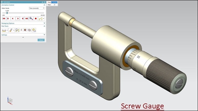
‘Screw Gauge’ Modelling & Simulation (Volume-1) Siemens NX 11 Tutorial

Screw Gauge_1

Screw Gauge_2

Screw Gauge_3

Serial No. 105-A.

'Screw Gauge' → Modelling & Simulation (Volume-1) Siemens NX 11 Tutorial

(Rest of the model is designed in Volume-2 & 3)


Click the following link to get the model file: - http://bit.ly/31XWlaD


Procedure of reading of Screw Gauge

Total number of divisions imprinted on Circular scale (in one round) = 25

Total number of divisions imprinted on Linear scale = 40

Pitch of Linear scale = total length of Linear scale/total number of divisions imprinted on Linear scale
= 25.4mm/40 = 0.635mm

Least count of Circular scale = Pitch of Linear scale/total number of divisions imprinted on Circular scale
= 0.635mm/25 = 0.0254mm

Reading of Linear scale = Pitch of Linear scale x Number of divisions opened on Linear scale
= 0.635mm x 4 = 2.54mm

Reading of Circular scale = Least count of Circular scale x Number of divisions
ahead of central line of Linear scale
= 0.0254mm x 2 = 0.0508mm

Total Reading = Reading of Linear scale + Reading of Circular scale
= 2.54mm + 0.0508mm = 2.5908mm

‘Screw Gauge’ Modelling & Simulation (Volume-2) Siemens NX 11 Tutorial

Screw Gauge_1

Screw Gauge_2

Screw Gauge_3

Serial No. 105-B.

'Screw Gauge' → Modelling & Simulation (Volume-2) Siemens NX 11 Tutorial

(Rest of the model is designed in Volume-1 & 3)


Click the following link to get the model file: - http://bit.ly/31XWlaD


Procedure of reading of Screw Gauge

Total number of divisions imprinted on Circular scale (in one round) = 25

Total number of divisions imprinted on Linear scale = 40

Pitch of Linear scale = total length of Linear scale/total number of divisions imprinted on Linear scale
= 25.4mm/40 = 0.635mm

Least count of Circular scale = Pitch of Linear scale/total number of divisions imprinted on Circular scale
= 0.635mm/25 = 0.0254mm

Reading of Linear scale = Pitch of Linear scale x Number of divisions opened on Linear scale
= 0.635mm x 4 = 2.54mm

Reading of Circular scale = Least count of Circular scale x Number of divisions
ahead of central line of Linear scale
= 0.0254mm x 2 = 0.0508mm

Total Reading = Reading of Linear scale + Reading of Circular scale
= 2.54mm + 0.0508mm = 2.5908mm

‘Screw Gauge’ Modeling & Simulation (Volume-3) Siemens NX 11 Tutorial

Screw Gauge_1

Screw Gauge_2

Screw Gauge_3

Serial No. 105-C.

'Screw Gauge' → Modeling & Simulation (Volume-3) Siemens NX 11 Tutorial

(Rest of the model is designed in Volume-1 & 2)


Click the following link to get the model file: - http://bit.ly/31XWlaD


Procedure of reading of Screw Gauge

Total number of divisions imprinted on Circular scale (in one round) = 25

Total number of divisions imprinted on Linear scale = 40

Pitch of Linear scale = total length of Linear scale/total number of divisions imprinted on Linear scale
= 25.4mm/40 = 0.635mm

Least count of Circular scale = Pitch of Linear scale/total number of divisions imprinted on Circular scale
= 0.635mm/25 = 0.0254mm

Reading of Linear scale = Pitch of Linear scale x Number of divisions opened on Linear scale
= 0.635mm x 4 = 2.54mm

Reading of Circular scale = Least count of Circular scale x Number of divisions
ahead of central line of Linear scale
= 0.0254mm x 2 = 0.0508mm

Total Reading = Reading of Linear scale + Reading of Circular scale
= 2.54mm + 0.0508mm = 2.5908mm

Friday, September 28, 2018

Modelling of 'Screw Gauge' with Dynamic Simulation (Volume-2) Autodesk Inventor 2018 Tutorial

Screw Gauge.jpg_1

Screw Gauge.jpg_2

Screw Gauge.jpg_3

Serial No. 305-B.

Modelling of 'Screw Gauge' with Dynamic Simulation (Volume-2) Autodesk Inventor 2018 Tutorial(Starting of the model is designed in Volume-1)


Click the following link to get the model file: - http://bit.ly/2oWAced


Procedure of reading of Screw Gauge

Total number of divisions imprinted on Circular scale (in one round) = 25

Total number of divisions imprinted on Linear scale = 40

Pitch of Linear scale = total length of Linear scale/total number of divisions imprinted on Linear scale
= 25.4mm/40 = 0.635mm

Least count of Circular scale = Pitch of Linear scale/total number of divisions imprinted on Circular scale
= 0.635mm/25 = 0.0254mm

Reading of Linear scale = Pitch of Linear scale x Number of divisions opened on Linear scale
= 0.635mm x 4 = 2.54mm

Reading of Circular scale = Least count of Circular scale x Number of divisions
ahead of central line of Linear scale
= 0.0254mm x 2 = 0.0508mm

Total Reading = Reading of Linear scale + Reading of Circular scale
= 2.54mm + 0.0508mm = 2.5908mm

Friday, February 10, 2017

Allen Screwdriver (Solid Edge ST9 Tutorial)


Allen Screwdriver_1

Allen Screwdriver_2

Serial No. 29

Allen Screwdriver (Solid Edge ST9 Tutorial)
In this Solid Edge Tutorial we will describe how to build the model ‘Allen Screwdriver’. The edge of Allen screwdriver has been constructed by different surface tools like Bound, Stitch, Derived etc. It is a Part and Assembly modelling tutorial. This assembly consist 2 part files Screw Driver and Handle that are positioned according to design intent by using Assembly Constraints.
It will cover the following topics.
........................................................................................................
• Creating 2D Sketches on different Planes.
• Use some sketch constraints as Connect, Horizontal/Vertical, and Equal etc. that are applied on during sketch creation.
• Use solid and surface feature command such as Revolved (Surface), Bounded, Stitched, Extrude, Cut, Circular Pattern, Loft, Subtract, Round etc.
• How to patterning an arc and a line by using ‘Derived’ command, this is the easiest way to create a sketch pattern.
• How to create a line by using ‘3D Line’ command in 3D Sketch environment.
• How to create a feature between circle and point by using ‘Loft Protrusion’ command.
• How to change the color of the model by using ‘Part Painter’ tool.
• How to insert component into the assembly using drag and drop from parts library by using ‘Insert Component’ command.
• How to mate the parts by using ‘Flash Fit’ command in the assembly.
• How to lock the rotation of the component by using ‘Lock Rotation’ option in ‘Flash Fit’ command in the assembly.
• Use the ‘Subtract’ command (Boolean) to remove the tool body volume from selected target bodies in the assembly. You can select multiple target bodies and multiple tool bodies.
• How to hide all components except the selected components by using ‘Isolate’ command in the assembly.

download-Link
  
Click the following link to get the model file: - http://bit.ly/2pWfHiu


Wednesday, February 8, 2017

Screw Driver (Solid Edge ST9 Tutorial)

Screw Driver_1

Screw Driver_2

Serial No. 28

Screw Driver (Solid Edge ST9 Tutorial)

In this Solid Edge Tutorial we will describe how to build the model ‘Screw Driver’. The edge of screw driver and handle has been constructed by different surface tools. It is a Part and Assembly modelling tutorial. This assembly consist 2 part files Screw Driver and Handle that are positioned according to design intent by using Assembly Constraints.

It will cover the following topics.

........................................................................................................

• Creating 2D Sketches on different Planes.

• Use some sketch constraints as Connect, Horizontal/Vertical, and Equal etc. that are applied on during sketch creation.

• Use solid and surface feature command such as Revolved (Surface), BlueSurf, Bounded, Stitched, Extrude, Cut, Circular Pattern, Loft, Mirror Copy Feature, Union, Round etc.

• How to change the color of the model by using ‘Part Painter’ tool.

• How to insert component into the assembly using drag and drop from parts library by using ‘Insert Component’ command.

• How to mate the parts by using ‘Flash Fit’ command in the assembly.

• How to lock the rotation of the component by using ‘Lock Rotation’ option in ‘Flash Fit’ command in the assembly.

• How to rotate and moving part by using ‘Drag Component’ command.


download-Link


Click the following link to get the model file: - http://bit.ly/2VnnxgE

Sunday, January 5, 2014

Creating a Realistic Thread (Autodesk Inventor 2013)

Creating a realistic thread in Autodesk Inventor
Video Tutorial with caption and audio narration
 
The Screw file displayed in the video is taken from our model ‘Knob of Switch’.


First of all get the model files required to complete this tutorial by visiting the following link:- http://bit.ly/32leYVx 


Transcription of Video

1. Open the part file of Screw.
2. Select the 'Thread' tool in the Modify panel of 3D Model tab.
3. 'Face' selection button is automatically activated in the Thread dialogue box.
4. Select blue cylindrical face of the Screw.
5. Click the Specification tab, here it has automatically detected features/values like 'Thread Type', 'Size', 'Designation', 'Class' and 'Right Hand thread'.
6. If anyone wants to change the properties/features, it can be edited very easily.
7. Click OK to apply the thread feature.
8. Select the 'Thread Modeler' tool in the Thread Modeler panel of Tools tab.
9. Select Thread feature in the Browser Bar.
10. The Thread Modeler tool has automatically detected the pitch of the thread in the Thread Modeler Control dialogue box.
11. Click OK to apply realistic thread on the screw.
.....................................................................................................................................................
Visit Autodesk exchange Apps site on the following link to get  the ‘Thread Modeler Tool’ which is an external application utilized with the software :-