Showing posts with label Solid Edge. Show all posts

Sunday, September 9, 2018

Application of 3D Sketch in Solid Edge ST9 (with caption and audio narration)

Application of 3D Sketch tool in Solid Edge

Serial No. 106

Application of 3D Sketch in Solid Edge ST9 (with caption and audio narration)

This partial design has been used in my model 'Bulb Shade (Solid Edge Tutorial)'. I tried to emphasize regarding the use of 3D Arc by 3 Points tool, simultaneously creating surface with the help of 'Bound' command.


Transcription of the Video

  1. Create a new sketch on XY plane.
  2. Draw the two circles coincident from the part origin.
  3. Apply the desired dimension.
  4. Apply the symmetric constraint on these two lines and give the angular dimension.
  5. Create a 3 Point Arc, between the intersection point of line and circle.
  6. Save the part file.
  7. Create a point H1 on the circle and which lie on the end point of the vertical line.
  8. Create a new Plane 1/2 inch below from XY plane along Z axis.
  9. Create a new sketch on Plane4.
  10. Create a point on Plane4 which is the project of point H1.
  11. In Sketch panel, click on 3D Sketch tool.
  12. In 3D Draw panel, click on 3D Arc by 3 Points tool.
  13. Select two endpoints A & B are on the arc of outer circle, and lie on XY Plane. Next, select point H2 which lies on Plane4 which is the project of point H1. (A, B and H1 are coplanar points and lies on XY Plane).
  14. Exit from the 3D sketch environment.
  15. Go to the Surfacing tab, in the Surfaces panel click on Bounded tool.
  16. Select the 3D Arc and Edge Set of (Sketch1).
  17. Click on finish button to create the surface.

Thursday, September 6, 2018

Creating a custom template in Solid Edge ST9 (with caption and audio narration)

Creating a custom template in Solid Edge ST9

Serial No. 105

Creating a custom template in Solid Edge ST9 (with caption and audio narration)


Transcription of the Video

  1. Create an ansi inch part file in Solid Edge ST9.
  2. 'Transition to Ordered' button should be activated, for creating an ordered modelling feature.
  3. Dimetric View is selected by default, but here I choose ISO View.
  4. Activate the 'Style' command.
  5. In the 'Style type' area choose Dimension.
  6. Click new button.
  7. Set the name as 'Fraction'.
  8. Under the Based on section select ANSI (in) option.
  9. Click the 'Units' tab and choose 1/16 inch in the 'Round-off' section list.
  10. Click OK and apply button.
  11. Activate the Solid Edge Options command.
  12. Change the Length and angular dimension value in Units tab.
  13. Previous settings is to be applied which have done earlier to create the new dimension style.
  14. Save the template file by giving it proper name, in a Solid Edge template folder.
  15. Once again, activate the Solid Edge Options command.
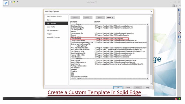
  16. Click File Locations button, select the 'User templates' option.
  17. Click Modify button and select my own created folder.
  18. Click OK.
  19. Open a new file in Solid Edge and check the result.
  20. Dimensions are shown in fraction due to selection of my previous setting.

Sunday, July 29, 2018

Suspension (Assembly Volume-2) Solid Edge ST9 Tutorial


Suspension_1

Suspension_2


Serial No. 75-B.


Suspension (Assembly Volume-2) Solid Edge ST9 Tutorial
In this Solid Edge ST9 Assembly tutorial, we have created a model named ‘Suspension’. The Assembly consist of 12 Subassemblies and 43 parts (modelled as well as standard parts) that are positioned according to design intent by using Assembly Constraints.
To complete this tutorial, first get the files used for creating the assembly.
This tutorial will give you a good practice of applying constraints in an assembly and give you an idea of suspension mechanism.
To watch the designing of assembly components, visit on following link:-
https://www.youtube.com/playlist?list=PLKWX3xUP3pPpRpkNsubaQdZuTGcNh1-MJ
………………………………………….
(Starting of the Assembly is designed in Volume-1)
The Design of the model ‘Suspension’ has been taken from Assembly file of 'Suspension' → ‘Sample files’ → Autodesk Inventor.


Click the following link to get the model file: - http://bit.ly/2OzRusu


Friday, December 1, 2017

Box (mini size) supported with Animation (Solid Edge ST9) with caption and audio narration

Box (mini size) with Animation


Serial No. 40

Box (mini size) supported with Animation (Solid Edge ST9) with caption and audio narration
.........................................................................
In this video, we will display how to create an animation of our model ‘Box (mini size)’ using ‘Simulate Motor’ command. In this model we have created two subassemblies, one is ‘Base Assembly’ & other is ‘Lid Assembly’ by using Assemble command.
.................................................................................
Inside this video, you can see the full detailed process of making 3-D Parametric CAD Model through Solid Edge ST9.


download-Link

  
Click the following link to get the model file: - http://bit.ly/2OuEHaM


Transcription of the Video

  1. Create a new inch assembly file.
  2. Save the file, name it as ‘Base Assembly’.
  3. Activate the ‘Insert Component’ command.
  4. Go to the ‘Parts Library’ tab and browse the folder ‘Box (mini size) with Animation’.
  5. Place the ‘Base Body’ part file in the assembly.
  6. Activate the ‘Insert Component’ command.
  7. Place the ‘Hook of Latch’ part file.
  8. ‘Assemble’ command is pre-activated by default when the part is placed in the assembly.
  9. Select the back face of Hook of Latch and the front face of the Base Body and apply the mate.
  10. Activate the ‘Assemble-Construction Display’ command.
  11. And choose ‘Show Reference Planes’ option.
  12. Open the visibility of reference planes of assembly.
  13. Apply a mate between the right plane of Hook of Latch and Base Body.
  14. Activate the ‘Planar Align’ command and set the offset value 0.688 inch.
  15. Apply a Planar Align mate between the top face of hook and base.
  16. Close the visibility of reference planes of assembly.
  17. Place the part file ‘Hinge’ and apply an axis mate between the inner circular face of Hinge and outer circular face of the base.
  18. Click ‘Flip Side’ button to rotate the part.
  19. Activate the ‘Flash Fit’ command, select the back face of Hinge and Base body and choose the flip side button to apply mate.
  20. Apply the Planar Align mate between Hinge and Base Body and set the offset value 2.564 inch.
  21. In the ‘Assemble’ command, ‘Flash Fit’ option is very useful tool in this software, for mating the assembly components easily in the assembly environment. This tool reduces the number of steps of the assembly relationships (like Mate, Planar Align and Axil Align mates etc.)
  22. In the same manner, fix one more Hinge on the Base Body.
  23. Open a new subassembly and place the Lid part file.
  24. Save the assembly, name it as ‘Lid Assembly’.
  25. Place the ‘Handle Base’ part file by using ‘Assemble’ command.
  26. Apply the mate between the back face of Handle Base and top face of Lid.
  27. Go to the Assemble tab and choose ‘Show Reference Planes’ option.
  28. The Planes of Handle Base are visible in the design window.
  29. Open the visibility of assembly planes.
  30. Apply the mate between the Right plane of Handle Base and Lid.
  31. Apply another mate between Front Plane of Handle Base and Lid.
  32. Close the visibility of all visible planes.
  33. In the same manner, place the ‘Wire’ part in the assembly and apply the mate.
  34. Go to the Inspect tab and check the Interference between ‘Wire’ and ‘Lid’ components by using ‘Check Interference’ command.
  35. Save the file and close all the subassemblies.
  36. Create a new inch assembly, this is our main assembly.
  37. Base Assembly and Lid Assembly will be placed in this assembly which has been created earlier.
  38. Save the file with the name ‘Box (mini size) with Animation’.
  39. Apply the Mate between the outer circular face of Wire and inner circular face of Hinge.
  40. Apply another mate between inner slot face of Lid and the front face of Hinge.
  41. Now drag the Lid subassembly by using ‘Drag Component’ command.
  42. The Lid Assembly starts to move on the base of Hinge.
  43. Check the Interference between ‘Lid Assembly’ and ‘Base Assembly’.
  44. Apply a tangent mate between the bottom face of Lid and cylindrical face of the Base Body part.
  45. Place the ‘Handle Wire’ part file.
  46. And select it, choose the Show/Hide Component option.
  47. Place the checkmark in the ‘Reference Planes’ On button and click OK.
  48. Close the visibility of Base assembly.
  49. Open the visibility of Right plane of Lid Assembly.
  50. Apply a Mate between the Right planes of Lid Assembly and Handle Wire.
  51. Apply a Connect mate between the axis of Handle Wire and the Front plane of Lid Assembly.
  52. Apply another Connect mate between the axis of Handle Wire and Plane 4 of Handle Base.
  53. Hide all the work planes in the assembly by using Show/Hide Component command.
  54. Rotate the handle to the proper position by using ‘Drag Component’ tool.
  55. Place the part file ‘Top of Latch’ in the assembly.
  56. Apply the mate constraint between Axis of Top of Latch and Wire.
  57. Apply another mate between the side face of Latch and inner slot face of Lid.
  58. Activate the ‘Angle’ mate command → select the front face of the latch → select the front face of the lid, and at last select side face of the lid and apply the mate.
  59. Select the Top of Latch part and set the angle mate value to 0-degree, click accept.
  60. Apply a Tangent mate between Handle Wire and the top face of Handle base.
  61. Three mates such as angle mate of Top of Latch, Tangent mate of Handle Wire and Tangent mate of Lid Assembly have to be Suppressed before going in the motion environment.
  62. Activate the ‘Rotational Motor’ command.
  63. ‘Select Moving Part Step’ option is preselected.
  64. Select the ‘Handle Wire’ part as moving part.
  65. Choose the ‘Select Axis Step’ option.
  66. Select the cylindrical face of ‘Handle Wire’, the part will rotate about the axis.
  67. Use the ‘Flip Direction’ button in reverse direction.
  68. Set the speed of motor 20 degree/sec and set the Limit value to 165.64 degrees.
  69. In the same manner, set the motor on the ‘Top of Latch’ and ‘Lid Assembly' by using ‘Rotational Motor’ command.
  70. Now see in the browser bar, three Rotational motion is visible under the Motors folder.
  71. Go to the Tools tab → ‘Environs’ panel and activate the ‘Explode-Render-Animate’ command.
  72. Activate the ‘Animation Editor’ command, the animation timeline is visible in the design window.
  73. Activate the ‘Animation Properties’ command and set the animation length value to 21 seconds.
  74. Click OK.
  75. Right-click on the ‘Motors’ and choose ‘Edit Definition’ option.
  76. In the Motor Group Properties dialogue box, three rotational motors are automatically added to the ‘Motors in Animation’ area.
  77. Click OK to execute the command.
  78. Now the three rotational motors are added in the animation timeline.
  79. Drag the Rotational Motor 2 and 3 at a convenient distance.
  80. Right-click the Rotational 1, click Properties.
  81. Change the value of start frame 16 seconds and click OK.
  82. Edit the properties of Rotational 2 and change the value of start frame 145 seconds and click OK.
  83. Edit the properties of Rotational 3 and change the value of start frame 232 seconds and click OK.
  84. Minimize the animation timeline.
  85. Zoom the view on the Handle Wire, Go on the ‘View Orientation’ tab and activate the ‘Save Current View’ command, name it as ‘View-2’.
  86. Zoom the view on the Top of Latch and save the current view name it as ‘View-3’.
  87. Maximise the animation timeline.
  88. In the same manner, create two more views as shown.
  89. Right-click on the ‘Camera’ and choose ‘Edit Definition’ option.
  90. In the ‘Camera Path Wizard’ dialogue box, activate the ‘Build using Named Views’ option.
  91. Add 4 views in the keyframes box.
  92. Click Finish button to execute the command.
  93. The camera patch is added to the animation timeline.
  94. Click ‘Go to Start’ button to set the animation cursor on starting position.
  95. Minimize the animation timeline and set the view as ‘View-1’ position.
  96. Right click on the animation timeline and choose ‘Insert Camera Location’ option.
  97. Move the animation cursor at 1 second and set the view as ‘View-2’ position.
  98. Right click on the animation timeline and choose ‘Insert Camera Location’ option.
  99. Delete the unused key by using ‘Delete key Frame’ command.
  100. Move the animation cursor at 8 seconds and set the view as ‘View-2’ position.
  101. Right click on the animation timeline and choose ‘Insert Camera Location’ option.
  102. Stay in still position on View-2 for 8 seconds.
  103. In the same manner, set the View-3 and View-4 on the Camera Path.
  104. Click ‘Play’ button and start the animation.
  105. Return back to the assembly environment and save the file.

Tuesday, September 5, 2017

Engine MKII (Volume-1) Solid Edge ST9 Tutorial


Engine MKII_1

Engine MKII_2

Serial No. 104-A.

Engine MKII (Volume-1) Solid Edge ST9 Tutorial

Engine MKII (Volume-1) Solid Edge Tutorial
The Design of this model has been taken from Assembly file of 'Rear Exhaust-2 Shoe' of ‘Sample files’ of Autodesk Inventor, it is a fragment of ‘Engine MKII’ Assembly.
(Rest of the Assembly is designed in Volume-2)
Rest components of the model ‘Engine MKII Assembly’ (consisting of several numbers) have also been designed. You may watch them by visiting on the following playlist:-
https://www.youtube.com/playlist?list=PLKWX3xUP3pPrb1bU6P_goEUCMvcfTuqtI
.................................................................................
In this Solid Edge ST9 Assembly tutorial, we have created a model named ‘Engine MKII’. The Assembly consist of 2 Subassemblies and 38 parts that are positioned according to design intent by using Assembly Constraints. Tutorial watch how an assembly of engine components is created by using different mates. The animation of internal components is also accomplished after setting all the components.
To complete this tutorial, first get the files used for creating the assembly.
This tutorial will give you a good practice of applying constraints in an assembly and give you an idea of Engine mechanism.
The video covers following assembly modelling techniques:--
_____________________________________________________________
• Use the Assembly commands such as Insert Components, Mate, and Drag Component with Triad tools etc.
• 38 Parts will be inserted with the help of ‘Insert Component’ tool.
• Use the Mate, Planer Align, Connect and Angle constraints between the two components etc.
• Check the interference between the two components by using ‘Check Interference’ tool.
• Save different state views of an assembly the internal components of engine easily by using the ‘Alternate Assemblies command.
• Animate the internal components like a piston, crank shaft, connecting rod of Engine with the help of Rotational Motor command in the Simulate Motor environment.


download-Link


Click the following link to get the model file: - http://bit.ly/2MtNAi6

Engine MKII (Volume-2) Solid Edge ST9 Tutorial

Engine MKII_1

Engine MKII_2

Serial No. 104-B.

Engine MKII (Volume-2) Solid Edge ST9 Tutorial

The Design of this model has been taken from Assembly file of 'Rear Exhaust-2 Shoe' of ‘Sample files’ of Autodesk Inventor, it is a fragment of ‘Engine MKII’ Assembly.
(Starting of the Assembly is designed in Volume-1)

Rest components of the model ‘Engine MKII Assembly’ (consisting of several numbers) have also been designed. You may watch them by visiting on the following playlist:-
https://www.youtube.com/playlist?list=PLKWX3xUP3pPrb1bU6P_goEUCMvcfTuqtI
.................................................................................
In this Solid Edge ST9 Assembly tutorial, we have created a model named ‘Engine MKII’. The Assembly consist of 2 Subassemblies and 38 parts that are positioned according to design intent by using Assembly Constraints. Tutorial watch how an assembly of engine components is created by using different mates. The animation of internal components is also accomplished after setting all the components.
To complete this tutorial, first get the files used for creating the assembly.
This tutorial will give you a good practice of applying constraints in an assembly and give you an idea of Engine mechanism.
The video covers following assembly modelling techniques:--
_____________________________________________________________
• Use the Assembly commands such as Insert Components, Mate, and Drag Component with Triad tools etc.
• 38 Parts will be inserted with the help of ‘Insert Component’ tool.
• Use the Mate, Planer Align, Connect and Angle constraints between the two components etc.
• Check the interference between the two components by using ‘Check Interference’ tool.
• Save different state views of an assembly the internal components of engine easily by using the ‘Alternate Assemblies command.
• Animate the internal components like an Engine Piston, Crank shaft, Connecting rod of Engine with the help of Rotational Motor command in the Simulate Motor environment.

download-Link


Click the following link to get the model file: - http://bit.ly/2MtNAi6

Friday, August 25, 2017

Miscellaneous Components of 'Engine MKII' (Solid Edge ST9 Tutorial)

Miscellaneous Components of 'Engine MKII'

Serial No. 103

Miscellaneous Components of 'Engine MKII' (Solid Edge ST9 Tutorial)

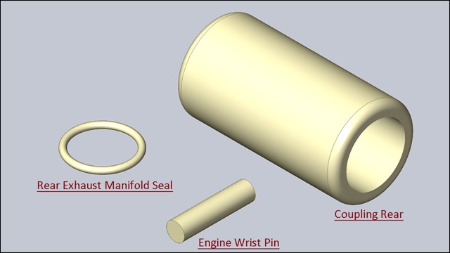
The Design of these components ‘Engine Wrist Pin’, 'Rear Exhaust Manifold Seal' and 'Coupling Rear', have been taken from Assembly file of 'Rear Exhaust-2 Shoe' of ‘Sample files’ of Autodesk Inventor, it is a fragment of ‘Engine MKII’ Assembly.
Rest components of the model ‘Engine MKII Assembly’ (consisting of several numbers) have also been designed. You may watch them by visiting on the following playlist:-
https://www.youtube.com/playlist?list=PLKWX3xUP3pPrb1bU6P_goEUCMvcfTuqtI
.......................................................................................
Inside this video, you can see the full detailed process of making 3-D Parametric CAD Model through Solid Edge ST9.

download-Link


Click the following link to get the model file: - http://bit.ly/2pa0r0N

Thursday, August 24, 2017

Extension Spring 3.873 (Solid Edge ST9 Tutorial)

Extension Spring 3.873

Serial No. 102

Extension Spring 3.873 (Solid Edge ST9 Tutorial)

The Design of the model ‘Extension Spring 3.873' has been taken from Assembly file of 'Rear Exhaust-2 Shoe' of ‘Sample files’ of Autodesk Inventor, it is a fragment of ‘Engine MKII’ Assembly.

Parameters are used to create the Extension Spring through Variables command.
Rest components of the model ‘Engine MKII Assembly’ (consisting of several numbers) have also been designed. You may watch them by visiting on the following playlist:-
https://www.youtube.com/playlist?list=PLKWX3xUP3pPrb1bU6P_goEUCMvcfTuqtI
.......................................................................................
Inside this video, you can see the full detailed process of making 3-D Parametric CAD Model through Solid Edge ST9.

download-Link


Click the following link to get the model file: - http://bit.ly/33mPFDz

Carb Spring (Solid Edge ST9 Tutorial)

Carb Spring

Serial No. 101

Carb Spring (Solid Edge ST9 Tutorial)

The Design of the model ‘Carb Spring' has been taken from Assembly file of 'Rear Exhaust-2 Shoe' of ‘Sample files’ of Autodesk Inventor, it is a fragment of ‘Engine MKII’ Assembly.
Rest components of the model ‘Engine MKII Assembly’ (consisting of several numbers) have also been designed. You may watch them by visiting on the following playlist:-
https://www.youtube.com/playlist?list=PLKWX3xUP3pPrb1bU6P_goEUCMvcfTuqtI
.......................................................................................
Inside this video, you can see the full detailed process of making 3-D Parametric CAD Model through Solid Edge ST9.

download-Link


Click the following link to get the model file: - http://bit.ly/30XR55x

Sunday, August 20, 2017

Flywheel Taper Collar (Solid Edge ST9 Tutorial)

Flywheel Taper Collar

Serial No. 100

Flywheel Taper Collar (Solid Edge ST9 Tutorial)

The Design of the model ‘Flywheel Taper Collar' has been taken from Assembly file of 'Rear Exhaust-2 Shoe' of ‘Sample files’ of Autodesk Inventor, it is a fragment of ‘Engine MKII’ Assembly.
Rest components of the model ‘Engine MKII Assembly’ (consisting of several numbers) have also been designed. You may watch them by visiting on the following playlist:-
https://www.youtube.com/playlist?list=PLKWX3xUP3pPrb1bU6P_goEUCMvcfTuqtI
.......................................................................................
Inside this video, you can see the full detailed process of making 3-D Parametric CAD Model through Solid Edge ST9.

download-Link


Click the following link to get the model file: - http://bit.ly/35kVV0h

Exhaust Manifold Gasket (Solid Edge ST9 Tutorial)

Exhaust Manifold Gasket

Serial No. 99

Exhaust Manifold Gasket (Solid Edge ST9 Tutorial)

The Design of the model ‘Exhaust Manifold Gasket' has been taken from Assembly file of 'Rear Exhaust-2 Shoe' of ‘Sample files’ of Autodesk Inventor, it is a fragment of ‘Engine MKII’ Assembly.
Rest components of the model ‘Engine MKII Assembly’ (consisting of several numbers) have also been designed. You may watch them by visiting on the following playlist:-
https://www.youtube.com/playlist?list=PLKWX3xUP3pPrb1bU6P_goEUCMvcfTuqtI
.......................................................................................
Inside this video, you can see the full detailed process of making 3-D Parametric CAD Model through Solid Edge ST9.

download-Link


Click the following link to get the model file: - http://bit.ly/324aOlq

Friday, August 18, 2017

Compression Button (Solid Edge ST9 Tutorial)

Compression Button_1

Compression Button_2

Serial No. 98.

Compression Button (Solid Edge ST9 Tutorial)

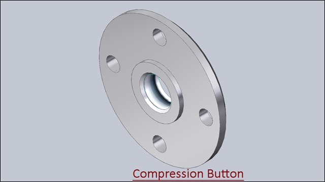
The Design of the model ‘Compression Button' has been taken from Assembly file of 'Rear Exhaust-2 Shoe' of ‘Sample files’ of Autodesk Inventor, it is a fragment of ‘Engine MKII’ Assembly.
Rest components of the model ‘Engine MKII Assembly’ (consisting of several numbers) have also been designed. You may watch them by visiting on the following playlist:-
https://www.youtube.com/playlist?list=PLKWX3xUP3pPrb1bU6P_goEUCMvcfTuqtI
.......................................................................................
Inside this video, you can see the full detailed process of making 3-D Parametric CAD Model through Solid Edge ST9.

download-Link


Click the following link to get the model file: - http://bit.ly/2Oz1VN6

Thursday, August 17, 2017

Flywheel Washer (Solid Edge ST9 Tutorial)

Flywheel Washer

Serial No. 97

Flywheel Washer (Solid Edge ST9 Tutorial)

The Design of the model ‘Flywheel Washer' has been taken from Assembly file of 'Rear Exhaust-2 Shoe' of ‘Sample files’ of Autodesk Inventor, it is a fragment of ‘Engine MKII’ Assembly.
Rest components of the model ‘Engine MKII Assembly’ (consisting of several numbers) have also been designed. You may watch them by visiting on the following playlist:-
https://www.youtube.com/playlist?list=PLKWX3xUP3pPrb1bU6P_goEUCMvcfTuqtI
.......................................................................................
Inside this video, you can see the full detailed process of making 3-D Parametric CAD Model through Solid Edge ST9.

download-Link


Click the following link to get the model file: - http://bit.ly/311ZDsh

Clutch Bell (Solid Edge ST9 Tutorial)

Clutch Bell_1

Clutch Bell_2

Serial No. 96.

Clutch Bell (Solid Edge ST9 Tutorial)

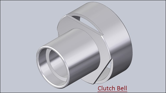
The Design of the model ‘Clutch Bell' has been taken from Assembly file of 'Rear Exhaust-2 Shoe' of ‘Sample files’ of Autodesk Inventor, it is a fragment of ‘Engine MKII’ Assembly.
Rest components of the model ‘Engine MKII Assembly’ (consisting of several numbers) have also been designed. You may watch them by visiting on the following playlist:-
https://www.youtube.com/playlist?list=PLKWX3xUP3pPrb1bU6P_goEUCMvcfTuqtI
.......................................................................................
Inside this video, you can see the full detailed process of making 3-D Parametric CAD Model through Solid Edge ST9.

download-Link


Click the following link to get the model file: - http://bit.ly/2M1K0Nl

Carb Slide (Solid Edge ST9 Tutorial)

Carb Slide

Serial No. 95

Carb Slide (Solid Edge ST9 Tutorial)

The Design of the model ‘Carb Slide' has been taken from Assembly file of 'Rear Exhaust-2 Shoe' of ‘Sample files’ of Autodesk Inventor, it is a fragment of ‘Engine MKII’ Assembly.
Rest components of the model ‘Engine MKII Assembly’ (consisting of several numbers) have also been designed. You may watch them by visiting on the following playlist:-
https://www.youtube.com/playlist?list=PLKWX3xUP3pPrb1bU6P_goEUCMvcfTuqtI
.......................................................................................
Inside this video, you can see the full detailed process of making 3-D Parametric CAD Model through Solid Edge ST9.

download-Link


Click the following link to get the model file: - http://bit.ly/2AZ1tj7

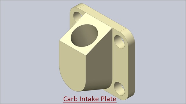
Carb Intake Plate (Solid Edge ST9 Tutorial)

Carb Intake Plate

Serial No. 94

Carb Intake Plate (Solid Edge ST9 Tutorial)

The Design of the model ‘Carb Intake Plate' has been taken from Assembly file of 'Rear Exhaust-2 Shoe' of ‘Sample files’ of Autodesk Inventor, it is a fragment of ‘Engine MKII’ Assembly.
Rest components of the model ‘Engine MKII Assembly’ (consisting of several numbers) have also been designed. You may watch them by visiting on the following playlist:-
https://www.youtube.com/playlist?list=PLKWX3xUP3pPrb1bU6P_goEUCMvcfTuqtI
.......................................................................................
Inside this video, you can see the full detailed process of making 3-D Parametric CAD Model through Solid Edge ST9.

download-Link


Click the following link to get the model file: - http://bit.ly/2VqDQt6

Monday, August 14, 2017

Carb High-speed Needle (Solid Edge ST9 Tutorial)

Carb Highspeed Needle_1

Carb Highspeed Needle_2

Serial No. 93.

Carb High-speed Needle (Solid Edge ST9 Tutorial)

The Design of the model ‘Carb Highspeed Needle' has been taken from Assembly file of 'Rear Exhaust-2 Shoe' of ‘Sample files’ of Autodesk Inventor, it is a fragment of ‘Engine MKII’ Assembly.
Rest components of the model ‘Engine MKII Assembly’ (consisting of several numbers) have also been designed. You may watch them by visiting on the following playlist:-
https://www.youtube.com/playlist?list=PLKWX3xUP3pPrb1bU6P_goEUCMvcfTuqtI
.......................................................................................
Inside this video, you can see the full detailed process of making 3-D Parametric CAD Model through Solid Edge ST9.

download-Link


Click the following link to get the model file: - http://bit.ly/33bkI4W

Sunday, August 13, 2017

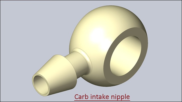
Carb intake nipple (Solid Edge ST9 Tutorial)

Carb intake nipple

Serial No. 92

Carb intake nipple (Solid Edge ST9 Tutorial)

The Design of the model ‘Carb intake nipple' has been taken from Assembly file of 'Rear Exhaust-2 Shoe' of ‘Sample files’ of Autodesk Inventor, it is a fragment of ‘Engine MKII’ Assembly.
Rest components of the model ‘Engine MKII Assembly’ (consisting of several numbers) have also been designed. You may watch them by visiting on the following playlist:-
https://www.youtube.com/playlist?list=PLKWX3xUP3pPrb1bU6P_goEUCMvcfTuqtI
.......................................................................................
Inside this video, you can see the full detailed process of making 3-D Parametric CAD Model through Solid Edge ST9.

2

download-Link


Click the following link to get the model file: - http://bit.ly/2AVpx6j

Friday, August 11, 2017

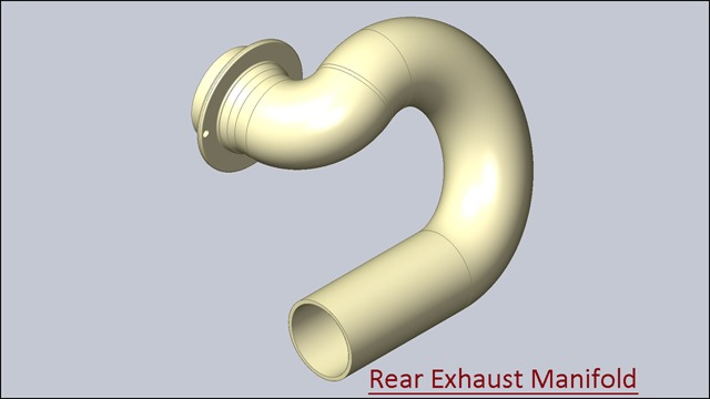
Rear Exhaust Manifold (Solid Edge ST9 Tutorial)

Rear Exhaust Manifold_1

Rear Exhaust Manifold_2

Serial No. 91.

Rear Exhaust Manifold (Solid Edge ST9 Tutorial)

The Design of the model ‘Rear Exhaust Manifold' has been taken from Assembly file of 'Rear Exhaust-2 Shoe' of ‘Sample files’ of Autodesk Inventor, it is a fragment of ‘Engine MKII’ Assembly.
Rest components of the model ‘Engine MKII Assembly’ (consisting of several numbers) have also been designed. You may watch them by visiting on the following playlist:-
https://www.youtube.com/playlist?list=PLKWX3xUP3pPrb1bU6P_goEUCMvcfTuqtI
.......................................................................................
Inside this video, you can see the full detailed process of making 3-D Parametric CAD Model through Solid Edge ST9.

download-Link


Click the following link to get the model file: - http://bit.ly/313I9M6

Engine Sleeve Rear (Solid Edge ST9 Tutorial)

Engine Sleve Rear_1

Engine Sleve Rear_2

Serial No. 90.

Engine Sleeve Rear (Solid Edge ST9 Tutorial)

The Design of the model ‘Engine Sleve Rear' has been taken from Assembly file of 'Rear Exhaust-2 Shoe' of ‘Sample files’ of Autodesk Inventor, it is a fragment of ‘Engine MKII’ Assembly.
Rest components of the model ‘Engine MKII Assembly’ (consisting of several numbers) have also been designed. You may watch them by visiting on the following playlist:-
https://www.youtube.com/playlist?list=PLKWX3xUP3pPrb1bU6P_goEUCMvcfTuqtI
.......................................................................................
Inside this video, you can see the full detailed process of making 3-D Parametric CAD Model through Solid Edge ST9.

download-Link


Click the following link to get the model file: - http://bit.ly/3212qTX