Showing posts with label Sweep Tool. Show all posts

Thursday, March 17, 2016

Pipe Fittings || Creo Parametric Tutorial

Pipe Fittings (1280x720)

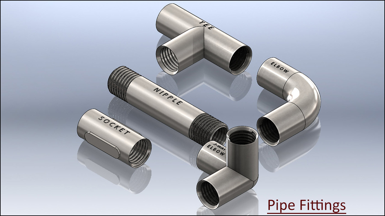
In this Creo Parametric tutorial, we will create the models of Pipe Fittings named Nipple, Socket, Elbow, Tee and Three Way Elbow.

This tutorial will give the intermediate-level user a good practice of Helical Sweep Tool along with Sweep Tool, Pattern/Geometry Pattern Tool, Extrude Tool, Shell Tool, Chamfer Tool, Mirror Tool, Creating Cross Sections and many 2D sketching techniques. .

download-Link
Visit the following link to find the files required to complete the tutorial along with finished model file:--
http://bit.ly/2N8AxTy

Creo Parametric Beginners Tutorial || Fork

Fork 1280x720

In this Creo Parametric tutorial, we will learn about the basic techniques that will give a beginner quick start-up knowledge of the software by developing a ‘Fork’ model. The model is the part of a Scooter Assembly.

The video demonstrates utilization of Extrude Tool, Shell Tool, Sweep Tool, Boundary Blend Tool, Mirror Tool, Round and Chamfer Tool along with basic 2D sketching.

download-Link


Get the model file by visiting the following link…
http://bit.ly/2Wbt1vl

Friday, April 17, 2015

Pipe Fittings (SolidWorks 2014 Tutorial)


Serial No. 115

Pipe Fittings (SolidWorks 2014 Tutorial)

We have added the audio on this video so that you can understand it this video more easily. Inside this Solidworks tutorial, viewers can watch the full detailed process of creating pipe fitting components which are 3-D Parametric CAD Models. In this video, we will demonstrate how to modelling of Pipe Fittings names such as Nipple, Socket, Elbow, Three-Way Elbow and Tee components. In modelling of this video, we have used BSP Thread sketch profile in the cutting of realistic thread. We have used Helix/Spiral and Swept cut tool for creating the thread over these components.

download-Link


Click the following link to get the model file: -http://bit.ly/30NucBQ


....................................................................................
Visit the following link to watch the basic tutorial on SolidWorks by us
https://www.youtube.com/playlist?list=PLb-IhKRMYSES3Zw3QHmQVqQ-rcFVzgYHy
.........................................................................
To watch more detailed tutorials on the same software visit the following link
https://www.youtube.com/playlist?list=PLKWX3xUP3pPo77gFCyy669sI76qJa5jKw
...................................................................................
Hope all of you enjoyed the tutorial. If you find the video useful please like it and share it with your friends/colleagues and do not forget to subscribe us to get latest updates about our new uploads.
http://www.youtube.com/user/nisheethsorjm?sub_confirmation=1
....................................................................................................
Dear Viewers if you like our work and wanted to support us, to keep continuing the good work, then become a patron of ours at ‘Patreon’ site. Patreon is a simple way for you to contribute to the creator’s work every month/ every time they release their new work and get rewards in return. Please visit the following link to know all about our work and what we are offering a reward to our patrons…
https://www.patreon.com/nisheethsri
...................................................................................................................................

Sunday, September 28, 2014

Chassis for Automatic Voltage Regulator by Sheet Metal (SolidWorks 2014 Tutorial)

Chassis for Automatic Voltage Regulator by Sheet Metal

Serial No. 17

Chassis for Automatic Voltage Regulator by Sheet Metal (SolidWorks 2014 Tutorial)


Inside this video, viewers will watch full detailed process of creating this model through SolidWorks Sheet Metal design functionality.

download-Link


Click the following link to get the model file: - http://bit.ly/2nIgKBQ

Monday, January 27, 2014

Application of ‘Sweep' tool and ‘Circular Pattern’ tool-Autodesk Inventor 2013 (with caption and audio)

Application of ‘Sweep’ tool and ‘Circular Pattern’ tool

Serial No. 198

Application of ‘Sweep' tool and ‘Circular Pattern’ tool-Autodesk Inventor 2013 (with caption and audio)

In this exercise we will create a new part named ‘Blade-base’, related to our previously created full-fledged model ‘Mixer (Cabinet)’.

In this part file we will utilize following feature/tools: - 2D Sketches, work planes, extrude, fillet, sweep and circular pattern.


download-Link 


Click the following link to get the model file: - http://bit.ly/2nMCMms


Transcription of Video

  1. Create a New Standard (in).ipt file.
  2. Create a new sketch on the XY Plane with the aid of ‘Create 2D Sketch’ tool.
  3. Draw the sketch diagram of part ‘Blade-base’ with the help of line tool.
  4. Pick up the Offset tool and select all lines in the graphics window.
  5. Enter the offset distance 1/16 inch between these two lines.
  6. Close the sketch profile by adding lines where the gap exists.
  7. Now the sketch is complete.
  8. Finish the 2D sketch.
  9. Select any one of the line of enclosed profile, the mini-toolbar will appear in the graphics window.
  10. Click the ‘Create Extrude’ icon.
  11. It will automatically select the enclosed profile.
  12. Extrude dialogue box is visible in the graphics window.
  13. In the Extents field, select ‘Symmetric’ option.
  14. Enter the distance value 3/8 inch.
  15. Click OK to create the extrude feature.
  16. Change the model colour to ‘Steel’.
  17. Save the file with the name ‘Blade-base’.
  18. Activate the Fillet tool from the Modify panel of 3D Model tab.
  19. Fillet dialogue box is visible in the graphics window.
  20. Select four bend edges of the model.
  21. Set the value to 1/16 inch in ‘Radius’ field.
  22. Click OK to create the fillet feature.
  23. Now make some changes in the settings of the software.
  24. Go to the Options panel of Tools tab and click Application Options icon.
  25. Application Options dialogue box is visible in the graphics window.
  26. General tab is active by default.
  27. Switch to Sketch tab.
  28. Click on the Standard Toggle box of 'Autoproject edges for sketch creation and edit' option.
  29. Apply and close the dialogue box.
  30. Create a new sketch on the blue face of the model, it will be used as a profile for the sweep.
  31. Select the projected model edges in the graphics window and convert them into construction geometry.
  32. Draw a line from Point1 of length 1/8 inch, parallel to Z direction of prevailing 3D indicator in the graphics window.
  33. Draw another line from the same Point1 of length 3/64 inch, parallel to Y direction.
  34. Close the profile by adding a new line.
  35. Finish the 2D Sketch.
  36. On the Ribbon click ‘Plane’ icon on the Work Features panel of 3D Model tab.
  37. Click on Point2 and select corresponding edge of the model (indicated by red colour).
  38. Work Plane has been created, perpendicular to this edge.
  39. Create a new sketch on this Work Plane to create a path for sweep.
  40. Right click in the graphics window and choose ‘Slice Graphics’ option.
  41. Take the project of the model by using ‘Project Cut Edges’ tool.
  42. Convert the entire projected model edges into construction geometry except yellow coloured line and arc.
  43. Add a new line starting from Point3 of length 0.75833 inch over the projected model edge indicated by yellow colour.
  44. Finish the 2D Sketch.
  45. Activate the ‘Sweep’ tool from Create panel of 3D Model tab.
  46. Sweep dialogue box is visible in the graphics window.
  47. Since there is only one closed profile, the profile drawn on Sketch2 is selected automatically.
  48. The Path selection button is active in the Sweep dialogue box.
  49. Select the sketch profile drawn on Sketch3 as sweep path in the graphics window.
  50. Select ‘Cut’ option to remove the material.
  51. Click OK to execute the Sweep feature.
  52. On the Ribbon click ‘Circular Pattern’ icon on the Pattern panel of 3D Model tab.
  53. Circular Pattern dialogue box is visible in the graphics window.
  54. In the Circular Pattern dialogue box, ‘Features’ selection button is activated by default.
  55. Select the ‘Sweep1’ in the Browser Bar as feature to pattern.
  56. Right click in the graphics window and choose Continue from the context menu.
  57. Select the Y Axis in the Browser Bar to define axis of revolution.
  58. Set the pattern count value 2 in the ‘Placement’ field.
  59. Leave the pattern angle 360 degree unchanged which is set by default.
  60. Click OK to execute the Circular Pattern feature.
  61. Create a new sketch on the blue face of ‘Blade-base’.
  62. Draw a square of length ¾ inch with the aid of ‘Three Point Centre Rectangle’ tool, coincident with autoprojected part origin.
  63. Activate the ‘Three Point Centre Rectangle’ from the Draw panel of Sketch tab.
  64. Click on Point4 to set the center point of the rectangle.
  65. Right click in the graphics window and click OK to finish the rectangle command.
  66. Exit the sketching environment.
  67. Activate the Extrude command from the marking menu.
  68. And select the square.
  69. In the Extents field, select ‘To’ option from the drop down list.
  70. Select back face of the model and choose Join option.
  71. Click OK to create Extrude feature.
  72. Create a new sketch once again on the blue face of model.
  73. Draw another square of length 3/16 inch.
  74. Use this square to remove material from the model by using Extrude tool.

Thursday, January 23, 2014

Application of ‘Sweep’ tool and ‘Shell’ tool-Autodesk Inventor 2013 (with caption and audio narration)

Application of ‘Sweep’ tool and ‘Shell’ tool

Serial No. 196

Application of ‘Sweep’ tool and ‘Shell’ tool-Autodesk Inventor 2013 (with caption and audio narration)

In this exercise we will create a new part, related to our previously created full-fledged model ‘Elbow’.

In this part file we will create some 2D Sketches, work planes, sweep & shell features.

 download-Link


Click the following link to get the model file: - http://bit.ly/2nPe9Wf


Transcription of Video

  1. Create a New Standard (in).ipt file.
  2. Create a 2D Sketch on the XY Plane.
  3. Draw a line of length 1.1875 inch, coincident with the auto projected part origin and parallel to X axis.
  4. Right click in the graphics window and select ‘Create Line’ tool.
  5. Click the green point in the graphics window as start point of the line.
  6. And enter the value 1.1875 inch.
  7. Right click in the graphics window and click OK to finish the command.
  8. Create another line of length 1.1875 inch, parallel to Y axis and coincident with the origin.
  9. Select these two lines and change the colour to White.
  10. On the Ribbon click ‘Fillet’ icon on the Draw panel of Sketch tab.
  11. 2D Fillet dialogue box is visible in the graphics window.
  12. Enter the value 0.625 inch in the 2D fillet dialogue box.
  13. And select these two lines in the graphics window to apply the fillet.
  14. Right click in the graphics window and click OK to exit the command.
  15. Finish the 2D Sketch.
  16. On the Ribbon click ‘Plane’ icon on the Work Features panel of 3D Model tab.
  17. Click one of the end points of the line and select this line in the graphics window.
  18. Work Plane has been created, perpendicular to this line.
  19. Create a new sketch on this Work Plane.
  20. Draw a Circle of diameter 1 inch on the end point of the line.
  21. Finish the 2D Sketch.
  22. Activate the ‘Sweep’ tool from Create panel of 3D Model tab.
  23. Sweep dialog box is visible in the graphics window.
  24. Since there is only single closed profile, the profile drawn on sketch 2 is selected automatically.
  25. The path selection button is active in the Sweep dialogue box.
  26. Select the ‘Sketch1’ in the graphics window as sweep path.
  27. Click OK to execute the Sweep feature.
  28. Change the model colour to ‘Flaked Reflective – Beige’.
  29. Save the Part file with the name ‘Elbow’.
  30. On the Ribbon click ‘Shell’ tool icon on the Modify panel of 3D Model tab.
  31. Shell dialog box is visible in the graphics window.
  32. ‘Remove Faces’ selection button is activated by default.
  33. Select both blue faces of the Elbow.
  34. Enter the value 0.125 inch in the ‘Thickness’ field.
  35. Click OK to apply the Shell feature.