Showing posts with label Elbow. Show all posts

Tuesday, April 14, 2020

Elbow Piston (Solid Edge ST9 Tutorial)

Serial No. 117

Elbow Piston along with Drawing Sheet (Solid Edge ST9 Tutorial)

Designing a machine part from the 2D sketch. Dear Viewers, In this video we will show how to create a 3D model 'Elbow Piston' with the help of 2D drawing sheet in Solid Edge Tutorial Software.


Download the 2D drawing sheet in PDF form by visiting the following link: -- https://bit.ly/2QFjjzK


Visit the following link to watch more tutorial on Solid Edge by us
https://www.youtube.com/playlist?list=PLKWX3xUP3pPq5ijHdni6jXNX445Il3MWJ
..........................................................................................
Hope all of you will enjoy the tutorial. If you find the video useful please like it and share it with your friends/colleagues and do not forget to subscribe us to get latest updates about our new uploads.
http://www.youtube.com/user/nisheethsorjm?sub_confirmation=1m
....................................................................................................
Dear Viewers if you like our work and wanted to support us, to keep continuing the good work, then become a patron of ours at ‘Patreon’ site. Patreon is a simple way for you to contribute to the creator’s work every month/ every time they release their new work and get rewards in return. Please visit the following link to know all about our work and what we are offering a reward to our patrons…
https://www.patreon.com/nisheethsri
.............................................................

Sunday, April 12, 2020

Flanged 90 Elbow (Siemens NX 1855 Tutorial)

Serial No. 122

Flanged 90 Elbow along with Drawing Sheet (Siemens NX 1855 Tutorial)

Designing a machine part from the 2D sketch. Dear Viewers, In this video we will show how to create a 3D model 'Flanged 90 Elbow' with the help of 2D drawing sheet in Siemens NX Software.


Download the 2D drawing sheet in PDF form by visiting the following link: -- http://bit.ly/39Il46H


.........................................................................
Visit the following link to watch more tutorial on Siemens NX by us
https://www.youtube.com/playlist?list=PLKWX3xUP3pPpUvtPuzEPoHimjTjpdbl_Q
.........................................................................
Hope all of you enjoyed the tutorial. If you find the video useful please like it and share it with your friends/colleagues and do not forget to subscribe me to get latest updates about my new uploads….
http://www.youtube.com/user/nisheethsorjm?sub_confirmation=1
....................................................................................................
Dear Viewers if you like our work and wanted to support us, to keep continuing the good work, then become a patron of ours at ‘Patreon’ site. Patreon is a simple way for you to contribute to the creator’s work every month/ every time they release their new work and get rewards in return. Please visit the following link to know all about our work and what we are offering as the reward to our patrons…
https://www.patreon.com/nisheethsri
.................................................................

Friday, August 24, 2018

'Elbow' SolidWorks 2014 Tutorial (with caption and audio narration)

Elbow

Serial No. 20

'Elbow' SolidWorks 2014 Tutorial (with caption and audio narration)

In this video, we create an Elbow by SolidWorks. In modelling of this part, Sweep Boss/Base, Shell, Helix/Spiral Curve, Circular Pattern, Fillet etc. tools are used. To cut thread, British Standard Pipe Thread profile is taken to be used.


  Click the following link to get the model file: - http://bit.ly/2nvXVBT


Transcription of the Video

  1. Open a new part file in SolidWorks.
  2. Activate the 'Edit Document Units' command.
  3. Set the digit in decimal up to 5 places and in fraction column-- 1/16 inches.
  4. Create a new sketch on the Top Plane.
  5. Draw the vertical and horizontal line from the part origin.
  6. Set the dimension of the line and convert it into construction geometry.
  7. Draw a 3 Point Arc, which lies on these two lines.
  8. Apply the radius of this arc and constraint it.
  9. Draw the line on the construction line.
  10. Exit the sketch.
  11. Create a new work-plane on this point of the line.
  12. Draw a circle on this plane.
  13. Activate the 'Swept Boss/Base' command.
  14. First select a circle as a profile and select the arc as a path.
  15. Click OK to finish the command.
  16. Activate the 'Shell' command.
  17. Select these two faces of the part and set the thickness value 1/8 inch.
  18. Save the part file, name it as 'Elbow'.
  19. Change the colour of the internal face of the model.
  20. Create a sketch on this face and take a project of this circular edge.
  21. Go to the 'Curves' panel and activate the 'Helix and Spiral' command.
  22. Select 'Sketch3' from feature manager design tree.
  23. Choose 'Height and Pitch' option.
  24. Select reverse direction and set height and pitch value.
  25. Click OK to finish the command.
  26. Create a new sketch on the Top Plane.
  27. Activate the section view button and choose Top Plane.
  28. Open 'BSP Thread Profile' part file.
  29. Copy the sketch profile and paste into the previous file.
  30. Take the project of helix curve and place the sketch on the endpoint of helix curve.
  31. Convert the helix curve into construction geometry.
  32. Finish the sketch and exit from the section view.
  33. Go to the 'Features' tab and activate the 'Swept Cut' command.
  34. First select BSP Thread Profile and then next select helix curve.
  35. Click OK to finish the command.
  36. Open the visibility of part origin.
  37. Activate the 'Axis' button.
  38. Create an Axis between origin point and Top Plane.
  39. Activate the 'Circular Pattern' command.
  40. First select the axis and then select the Cut-Sweep1 feature.
  41. Set the angle 270 degree and choose reverse direction.
  42. Click OK to finish the command.
  43. Apply the fillet on these two edges.

Friday, April 17, 2015

Pipe Fittings (Autodesk Inventor 2013)


Serial No. 31
Pipe Fittings (Autodesk Inventor 2013)

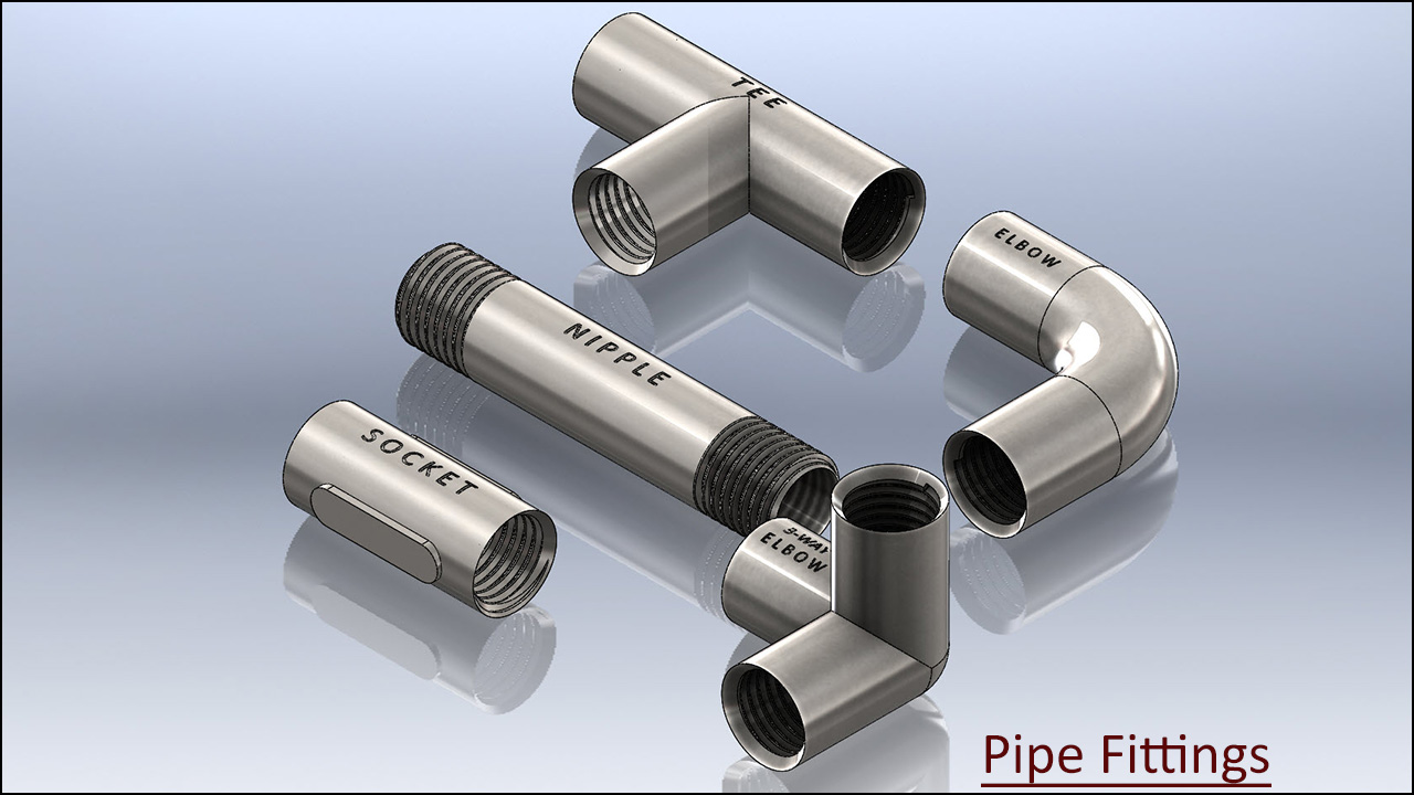
We have added the audio on this video so that you can understand it this video more easily. Inside this Autodesk Inventor tutorial, viewers can watch the full detailed process of creating pipe fitting components which are 3-D Parametric CAD Models. In this video, we will demonstrate how to modelling of Pipe Fittings names such as Nipple, Socket, Elbow, Three-Way Elbow and Tee components. In modelling of this video, we have used NPT Thread sketch profile in the cutting of realistic thread. We have used Coil tool for creating the thread over these components.


download-Link 


Click the following link to get the model file: -http://bit.ly/2lAUt81


....................................................................................................
Visit the following link to watch the basic tutorial on Autodesk Inventor by us
https://www.youtube.com/playlist?list=PLb-IhKRMYSERYpB48aY-sZ10fN6CfXIL4
.........................................................................
To watch detailed tutorials on the same software visit the following link
https://www.youtube.com/playlist?list=PL74BDF7431ED13443
..........................................................................................
Hope all of you enjoyed the tutorial. If you find the video useful please like it and share it with your friends/colleagues and do not forget to subscribe us to get latest updates about our new uploads.
http://www.youtube.com/user/niveshandnisheeth?sub_confirmation=1
....................................................................................................
Dear Viewers if you like our work and wanted to support us, to keep continuing the good work, then become a patron of ours at ‘Patreon’ site. Patreon is a simple way for you to contribute to the creator’s work every month/ every time they release their new work and get rewards in return. Please visit the following link to know all about our work and what we are offering as the reward to our patrons…
https://www.patreon.com/nisheethsri+

Pipe Fittings (SolidWorks 2014 Tutorial)


Serial No. 115

Pipe Fittings (SolidWorks 2014 Tutorial)

We have added the audio on this video so that you can understand it this video more easily. Inside this Solidworks tutorial, viewers can watch the full detailed process of creating pipe fitting components which are 3-D Parametric CAD Models. In this video, we will demonstrate how to modelling of Pipe Fittings names such as Nipple, Socket, Elbow, Three-Way Elbow and Tee components. In modelling of this video, we have used BSP Thread sketch profile in the cutting of realistic thread. We have used Helix/Spiral and Swept cut tool for creating the thread over these components.

download-Link


Click the following link to get the model file: -http://bit.ly/30NucBQ


....................................................................................
Visit the following link to watch the basic tutorial on SolidWorks by us
https://www.youtube.com/playlist?list=PLb-IhKRMYSES3Zw3QHmQVqQ-rcFVzgYHy
.........................................................................
To watch more detailed tutorials on the same software visit the following link
https://www.youtube.com/playlist?list=PLKWX3xUP3pPo77gFCyy669sI76qJa5jKw
...................................................................................
Hope all of you enjoyed the tutorial. If you find the video useful please like it and share it with your friends/colleagues and do not forget to subscribe us to get latest updates about our new uploads.
http://www.youtube.com/user/nisheethsorjm?sub_confirmation=1
....................................................................................................
Dear Viewers if you like our work and wanted to support us, to keep continuing the good work, then become a patron of ours at ‘Patreon’ site. Patreon is a simple way for you to contribute to the creator’s work every month/ every time they release their new work and get rewards in return. Please visit the following link to know all about our work and what we are offering a reward to our patrons…
https://www.patreon.com/nisheethsri
...................................................................................................................................

Thursday, January 23, 2014

Application of ‘Sweep’ tool and ‘Shell’ tool-Autodesk Inventor 2013 (with caption and audio narration)

Application of ‘Sweep’ tool and ‘Shell’ tool

Serial No. 196

Application of ‘Sweep’ tool and ‘Shell’ tool-Autodesk Inventor 2013 (with caption and audio narration)

In this exercise we will create a new part, related to our previously created full-fledged model ‘Elbow’.

In this part file we will create some 2D Sketches, work planes, sweep & shell features.

 download-Link


Click the following link to get the model file: - http://bit.ly/2nPe9Wf


Transcription of Video

  1. Create a New Standard (in).ipt file.
  2. Create a 2D Sketch on the XY Plane.
  3. Draw a line of length 1.1875 inch, coincident with the auto projected part origin and parallel to X axis.
  4. Right click in the graphics window and select ‘Create Line’ tool.
  5. Click the green point in the graphics window as start point of the line.
  6. And enter the value 1.1875 inch.
  7. Right click in the graphics window and click OK to finish the command.
  8. Create another line of length 1.1875 inch, parallel to Y axis and coincident with the origin.
  9. Select these two lines and change the colour to White.
  10. On the Ribbon click ‘Fillet’ icon on the Draw panel of Sketch tab.
  11. 2D Fillet dialogue box is visible in the graphics window.
  12. Enter the value 0.625 inch in the 2D fillet dialogue box.
  13. And select these two lines in the graphics window to apply the fillet.
  14. Right click in the graphics window and click OK to exit the command.
  15. Finish the 2D Sketch.
  16. On the Ribbon click ‘Plane’ icon on the Work Features panel of 3D Model tab.
  17. Click one of the end points of the line and select this line in the graphics window.
  18. Work Plane has been created, perpendicular to this line.
  19. Create a new sketch on this Work Plane.
  20. Draw a Circle of diameter 1 inch on the end point of the line.
  21. Finish the 2D Sketch.
  22. Activate the ‘Sweep’ tool from Create panel of 3D Model tab.
  23. Sweep dialog box is visible in the graphics window.
  24. Since there is only single closed profile, the profile drawn on sketch 2 is selected automatically.
  25. The path selection button is active in the Sweep dialogue box.
  26. Select the ‘Sketch1’ in the graphics window as sweep path.
  27. Click OK to execute the Sweep feature.
  28. Change the model colour to ‘Flaked Reflective – Beige’.
  29. Save the Part file with the name ‘Elbow’.
  30. On the Ribbon click ‘Shell’ tool icon on the Modify panel of 3D Model tab.
  31. Shell dialog box is visible in the graphics window.
  32. ‘Remove Faces’ selection button is activated by default.
  33. Select both blue faces of the Elbow.
  34. Enter the value 0.125 inch in the ‘Thickness’ field.
  35. Click OK to apply the Shell feature.