Showing posts with label SolidWorks 2014. Show all posts

Sunday, December 31, 2017

Animation displayed in 'Nose Pliers' Assembly--SolidWorks 2017 (with caption and audio narration)

Animation displayed in Nose Pliers

Serial No. 32

Animation displayed in 'Nose Pliers' Assembly--SolidWorks 2017 (with caption and audio narration)

In this video, we will demonstrate how to apply the different type of mates in the assembly environment for creating the animation.
..................................................................................
To watch full sketching video of this model 'Nose Pliers', please visit on my another associated video named as 'Nose Pliers' (Video Tutorial) SolidWorks.

download-Link


Click the following link to get the model file: - http://bit.ly/2oUp3Lb


Transcription of the Video

  1. Create a new assembly inside an English template.
  2. The ‘Begin Assembly’ command is preactivated in the assembly design window.
  3. Place the ‘Part1’ file in the assembly.
  4. Save the assembly, name it as ‘Nose Pliers with Animation’.
  5. When the first part file is placed in the assembly, the part remains as a grounded component.
  6. So we will do unground the part with the help of ‘Float’ option.
  7. Right-click on the ‘Part1’ file and choose ‘Float’ option.
  8. Drag the part and select it, choose ‘Edit Part’ option from the design window.
  9. Go to the model tree and open the visibility of ‘Axis1’.
  10. The Axis is not visible in the design window, so we will turn on the ‘Axes’ button.
  11. Now the axis is visible in the design window.
  12. Return back to the assembly environment.
  13. Apply a ‘Coincident’ mate between the Top Plane of Assembly and Top Plane of ‘Part1’.
  14. Apply another ‘Coincident’ mate between the Axis1 of ‘Part1’ and Origin point of the Assembly.
  15. Activate the ‘Insert Component’ command, place the ‘Part2’ file in the assembly.
  16. Rotate the part by using ‘Move with Triad’ command.
  17. Apply a ‘Concentric’ mate between the two holes of the Part.
  18. Apply a ‘Coincident’ mate between the inside face of the slot of ‘Part1’ and inside face of the slot of ‘Part2’.
  19. Place the ‘Revit’ file in the assembly.
  20. Select the ‘Revit’ file and rotate to the proper position.
  21. Apply a ‘Concentric’ mate between inside cylindrical face of ‘Revit’ and inside cylindrical face of the hole of ‘Part2’.
  22. Apply a ‘Coincident’ mate between inside face of the ‘Part2’ and back face of ‘Revit’.
  23. Apply a ‘Coincident’ mate between Front Plane of ‘Revit’ and Right Plane of the assembly.
  24. Drag the ‘Part1’ file and activate the Mate command.
  25. Different types of mates are available here, choose any mate as you need according to your design.
  26. Select the ‘Angle’ mate option and set the angle value 0 deg.
  27. Select the face of ‘Part1’ and Right Plane of assembly, select the ‘Anti-Aligned’ button under the Mate alignment option.
  28. Choose the ‘Flip dimension’ option and click OK to execute the command.
  29. In the same manner, apply another ‘Angle’ mate on the opposite side of the part.
  30. Now the assembly component is fulley defined in the assembly.
  31. Suppress the ‘Angle2’ mate.
  32. Activate the ‘Move Component’ command and select the ‘Collision Detection’ option.
  33. Drag the part until it touches the opposite part.
  34. Now highlighted face shows here to stop the motion of the component at the moment of touch of any other entity.
  35. Click OK to finish the command.
  36. Go to the Evaluate tab and activate the ‘Measure’ command.
  37. Measure the angle between these two edges of the part.
  38. Activate the ‘Interference Detection’ command.
  39. And check the interference between the two components.
  40. Unsuppress the ‘Angle2’ mate.
  41. Go to the ‘Motion Study’ tab, click the ‘Expand Motion Manager’ button.
  42. Right-click on the ‘Orientation and Camera Views’ option, select the ‘Disable Playback of View Keys’ option.
  43. Go to the ‘Mates’ folder, select the ‘Angle1’ mate and move the timebar at 10 second.
  44. Right-click on the animation timeline and place the new key by using ‘Place Key’ command.
  45. Modify this new key and paste the angle value 69.78676/2 deg. and click OK.
  46. Move the timebar at 13 second and place the new key.
  47. Pause the animation for 3 seconds.
  48. Move the timebar at 23 second and place the new key.
  49. Modify this new key, fill the value 0 deg. and click OK.
  50. Follow the same steps which were done earlier to create the animation for ‘Angle2’ mate.
  51. Click the ‘Calculate’ button to check the animation.
  52. Stop the animation and clear the screen to view full screen of the model.
  53. At the last, click ‘Play from Start’ button to see the result.

Wednesday, December 27, 2017

Animation displayed in 'Combination Pliers' Assembly--SolidWorks 2014 (with caption and audio narration)

Animation by Precise Positioning in Combination Pliers

Serial No. 33

Animation displayed in 'Combination Pliers' Assembly--SolidWorks 2014 (with caption and audio narration)

In this video, we will demonstrate how to apply the different type of mates in the assembly environment for creating the animation.

………………………………………………………………………………

To watch full sketching video of this model 'Combination Pliers', please visit on my another associated video named as 'Combination Pliers' (Video Tutorial) SolidWorks.

download-Link


Click the following link to get the model file: - http://bit.ly/2oyA2ti


Transcription of the Video

  1. Create a new assembly inside an English template.
  2. The ‘Begin Assembly’ command is preactivated in the assembly design window.
  3. Place the ‘Part1’ file in the assembly.
  4. When the first part file is placed in the assembly, the part remains as a grounded component.
  5. So we will do unground the part with the help of ‘Float’ option.
  6. Right-click on the ‘Part1’ file and choose ‘Float’ option.
  7. Rotate the part by using ‘Move with Triad’ command.
  8. Save the assembly, name it as ‘Combination Pliers with Animation’.
  9. Select the part file in the design window and choose ‘Edit Part’ option.
  10. Go to the design tree, open the visibility of ‘Axis1’ and go on the ‘View’ tab and turn on the ‘Axes’ button.
  11. The Axis is shown in the design window.
  12. Return back to the assembly environment.
  13. Apply a ‘Coincident’ mate between the Top Plane of Assembly and Top Plane of ‘Part1’.
  14. Apply another ‘Coincident’ mate between the Axis1 of ‘Part1’ and Origin point of the Assembly.
  15. Activate the ‘Insert Component’ command, place the ‘Part2’ file in the assembly.
  16. Apply a ‘Concentric’ mate between the two holes of the Part.
  17. Apply a ‘Coincident’ mate between the inside face of the slot of ‘Part2’ and inside face of the slot of ‘Part1’.
  18. Drag the Plier to see the effect, the part moves on its own axis.
  19. Place the ‘Part3’ file in the assembly.
  20. Select the ‘Part3’ file and rotate to the proper position.
  21. Apply a ‘Concentric’ mate between inside cylindrical face of ‘Part3’ and inside cylindrical face of the hole of ‘Part1’.
  22. Apply a ‘Coincident’ mate between inside face of the ‘Part1’ and back face of ‘Part3’.
  23. Close the visibility of ‘Axis1’.
  24. Go to the View tab and turn on the ‘Planes’ button.
  25. Open the visibility of Right Plane of the assembly.
  26. Apply an ‘Angle’ mate on this face and Right Plane of the assembly.
  27. Set the angle value 0 degree and click OK.
  28. In the same way, apply another ‘Angle’ mate on the opposite side of the part.
  29. Apply a ‘Coincident’ mate between Right Plane of the ‘Part3’ and Right Plane of the assembly.
  30. Go to the ‘Mates’ folder and Suppress the ‘Angle2’ mate.
  31. Activate the ‘Move Component’ command and select the ‘Collision Detection’ option.
  32. Drag the part until touch to the opposite part.
  33. Now highlighted face shows here to stop the motion of the component at the moment of touch of any other entity.
  34. Click OK to finish the command.
  35. Go to the ‘Evaluate’ tab, measure the angle between these two edges of the part by using ‘Measure’ command.
  36. Activate the ‘Interference Detection’ command and check interference between the two components.
  37. Unsuppress the ‘Angle2’ mate.
  38. Go to the ‘Motion Study’ tab and click on the ‘Disable Playback of View Keys’ option on the animation timeline.
  39. Go to the Mates folder, select ‘Angle1’ mate and drag the timebar at 10 second.
  40. Modify the ‘Angle1’ mate key, fill the angle value to 20.077055 deg. and click OK.
  41. Drag the timebar at 13 second and right-click on the timeline, click ‘Place Key’ option.
  42. Pause the animation for 3 seconds.
  43. Drag the timebar at 23 second, double click on the ‘Angle1’ mate and fill the value 0 deg. in the Modify dialogue box, click OK.
  44. Repeat same steps which were done earlier for creating the animation of ‘Angle2’ mate.
  45. Click the ‘Collapse Motion Manager’ button.
  46. Now start the animation to see the result.
  47. Save the assembly.

Friday, December 1, 2017

Animation displayed in Ceiling Hook -- SolidWorks 2014 (with caption and audio narration)

Ceiling Hook---1

Serial No. 214


Animation displayed in Ceiling Hook -- SolidWorks 2014 (with caption and audio narration)

In this video, we will demonstrate how to apply the different type of mates in the assembly environment for creating the animation.
..................................................................................
To watch full sketching video of this model 'Ceiling Hook', please visit on my another associated video named as 'Ceiling Hook with Animation' (SolidWorks).


download-Link


Click the following link to get the model file: - http://bit.ly/31K8Bvu 


Transcription of the Video
  1. Create a new assembly file.
  2. The ‘Begin Assembly’ command is already activated in the assembly design window.
  3. Click Browse button, place the part file ‘Hook’.
  4. First of all, open the visibility of ‘View Origin’ of the assembly.
  5. Click the View Origin point button to place the file, centre of the assembly.
  6. Choose ‘Isometric View’.
  7. In the same way, place one more part file-name ‘Circular Ring.’
  8. Rotate the part by using ‘Move with Triad’ tool.
  9. Save the assembly with the name ‘Ceiling Hook’ and edit the ‘Hook’ part file.
  10. Create a new sketch over the ‘Front Plane’ and take a project of this circular edge by using ‘Convert Entities’ command.
  11. Finish the sketch and return back to the assembly environment.
  12. Select the Front Plane of assembly and Right Plane of Circular Ring and mate it.
  13. It will apply a Coincident mate.
  14. Move the Circular Ring slightly.
  15. Activate the ‘Mate’command, select tangent face of Circular Ring and arc along the path of hook, and apply the tangent mate.
  16. Select the Front Plane of Circular Ring, Right Plane of assembly and apply the Coincident mate.
  17. Edit the Circular Ring part and activate the Axis tool.
  18. Choose ‘Point and Face/Plane’ option as this particular type of selection.
  19. Many options available here, choose any option as you need.
  20. Select the origin point and Front Plane of assembly to create the axis.
  21. Click OK to execute the command.
  22. Open the visibility of axis by using ‘View Axes’ command.
  23. Return to the assembly view.
  24. Activate the ‘Mate’ command, select the assembly origin and Axis of Circular Ring and apply it.
  25. Select the Coincident2 mate and suppress the mate.
  26. Let see here, the Circular ring part rotates about the inner periphery of Hook with the help of tangent and axis mate.
  27. Create an Axis between origin point of assembly and end point of arc in assembly.
  28. Create a new work plane between front plane and this axis.
  29. A work plane has been created along the axis.
  30. Apply an angle mate between Front plane of Circular Ring and Plane1.
  31. Set the angle value to 0 degree.
  32. Go on the Evaluate tab and activate the ‘Measure’ command.
  33. Select the Top Plane and Plane1 and monitor the value.
  34. Copy the angle value and calculate the value as shown (290.39126 degree).
  35. In the next section, we will create animation on the Circular Ring its start value is 00 and end value 290.391260.
  36. Choose Front View, in the Orientation dialog box, activate the ‘New view’ command and set its name as ‘View2'.
  37. In the same manner, choose Isometric View, set its name as ‘View1’.
  38. These saved views will be used later in animation timeline.
  39. Select the Motion Study tab, click the Orientation and Camera button in the animation timeline.
  40. Right click on the time bar and select Move Time Bar option, set the time on 2 second.
  41. Copy the View-1 key and place the key on 2 seconds.
  42. Pause 2 seconds on the View-1 position.
  43. Move the time bar on 7 seconds and add the new key.
  44. Minimize the animation timeline and choose View-2, in the Orientation dialog box.
  45. Return back to the animation timeline and right click over the 7 seconds key and select ‘Replace Key’ option.
  46. Time taken 5 seconds in changing from view-1 to view-2 position.
  47. In the Mates folder, select the Angle1 mate and add the key in the timeline by using Add key button.
  48. Right click the animation timeline, move the time bar at 22 seconds.
  49. Right click on the Angle1 and select Edit Dimension option, paste the specified angle, click OK.
  50. Click the ‘Collapse Motion Manager’ button.
  51. Click play animation button to check the motion.
  52. Now we will create some modifications in the animation.
  53. Right click the start key point time of angle mate and move the key position at 9 seconds in the Edit time dialogue box.
  54. Right click the end key point time of angle mate and move the key position at 24 seconds.
  55. Stop the animation 2 seconds between View-2 and starting key point of Angle1 mate.
  56. Go on the Orientation and Camera tab, copy the View-2 key and paste the key over 24 seconds in the timeline.
  57. Move the time bar at 26 seconds, right click and paste View-2 key.
  58. Pause the animation for 2 seconds at View-1 position.
  59. Copy the end key point of Angle1 mate and paste key on 26 seconds.
  60. Stay in the still position for 2 seconds.
  61. Repeat the whole animation in reverse order to come back in starting position.
  62. Minimize the animation timeline and clear the screen.
  63. Click ‘Play from Start’ button and start the animation.
  64. Return back to the assembly environment and save the file.

Square Bend Tube through Sheet Metal -- SolidWorks 2014 Tutorial (with caption and audio narration)

Square Bend Tube created through Sheet Metal


Serial No. 15

Square Bend Tube through Sheet Metal -- SolidWorks 2014 Tutorial (with caption and audio narration)

Inside this video, viewers will watch the full detailed process of creating this model through SolidWorks Sheet Metal design functionality.


download-Link


Click the following link to get the model file: - http://bit.ly/2uvJjpt 


Transcription of the Video

  1. Create a new Part file.
  2. Go to the ‘Edit Document Units’ tab and select ‘MMGS’ option.
  3. Create a new sketch over the Front Plane.
  4. Create a centre rectangle coincident with the origin and affix the dimensions.
  5. Select a horizontal line and convert into construction geometry.
  6. Draw two horizontal lines and apply the dimensions.
  7. Finish the sketch and choose the Isometric view.
  8. Save the file with the name ‘Square Bend Tube’.
  9. Create a new sketch over the Right Plane.
  10. Select the Right Plane and choose ‘Normal To’ option to rotate the view along the plane.
  11. Create a horizontal line and Vertical line with the preferred dimension.
  12. Create another line and set the angular dimension.
  13. Select these two lines and apply the equal constraint.
  14. Convert the four lines into construction geometry.
  15. Create two arcs between the endpoint of lines.
  16. Finish the sketch and activate the ‘Swept Flange’ command.
  17. In the Profile selection area, select the rectangle in the graphics area.
  18. In the Path selection area, select the line.
  19. The preview of swept is visible in the design window.
  20. Set the thickness value 2mm and bend radius value 2mm.
  21. Click OK to execute the command.
  22. Change the colour of the model as according to your choice.
  23. Change the color of selected curved face of the model to distinguish it for Emboss text.
  24. Create a new sketch on this face.
  25. Activate the ‘Convert Entities’ command.
  26. Select the two vertical edges of the model.
  27. Create a horizontal line and apply dimensions.
  28. Activate the ‘Text’ command and select the line.
  29. Write the text as ‘Square Bend Tube’ and format the text.
  30. Click OK to create the text.
  31. Choose the Isometric View.
  32. Activate the ‘Wrap’ command, select the horizontal line which is based on the text.
  33. And select this face for wrap the text.
  34. ‘Emboss’ option is preselected, if you want to engrave the text you choose ‘Deboss’ option.
  35. You may also change height of embossed text.
  36. Click OK to execute the command.
  37. Change the color of face for good looking.
  38. In the same manner, emboss the text opposite side of the model.
  39. Save the Part file.

Sunday, September 25, 2016

Creating Miter Flange (Video Tutorial with Caption) SolidWorks 2014

Creating Miter Flange

Serial No. 212

Creating Miter Flange (Video Tutorial with Caption) SolidWorks 2014

This tutorial shows how to create Miter Flange by selecting a linear edge of the sheet in solid works sheet metal environment.

download-Link
  

Click the following link to get the model file: -http://bit.ly/2OmYKYI


Transcription of the Video
  1. Creating Miter Flange in SolidWorks
  2. Activate the ‘Miter Flange’ command.
  3. Hold the mouse and read the message on dialog box.
  4. Draw two lines, perpendicular to each other on the front face of the model.
  5. Give the dimension to fully constraint the sketch.
  6. Uncheck the ‘Use default radius’ option in Miter Parameters panel, enter the value in the Bend Radius field.
  7. Select ‘Material Inside’ option under type 'Flange position'.
  8. Enter the value in the Gap distance field.
  9. Select the three inside linear edges to attach the miter flange.
  10. Finally the Miter Flange feature has been created successfully.

Friday, April 17, 2015

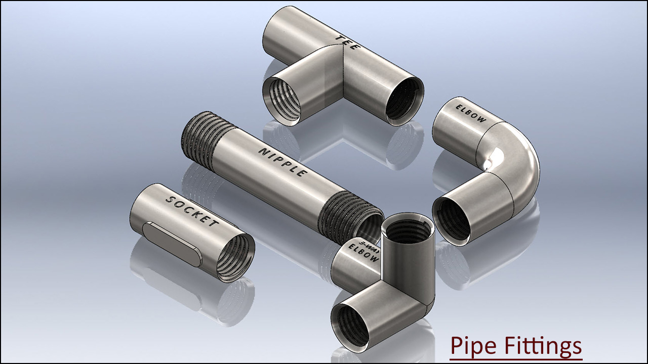
Pipe Fittings (SolidWorks 2014 Tutorial)


Serial No. 115

Pipe Fittings (SolidWorks 2014 Tutorial)

We have added the audio on this video so that you can understand it this video more easily. Inside this Solidworks tutorial, viewers can watch the full detailed process of creating pipe fitting components which are 3-D Parametric CAD Models. In this video, we will demonstrate how to modelling of Pipe Fittings names such as Nipple, Socket, Elbow, Three-Way Elbow and Tee components. In modelling of this video, we have used BSP Thread sketch profile in the cutting of realistic thread. We have used Helix/Spiral and Swept cut tool for creating the thread over these components.

download-Link


Click the following link to get the model file: -http://bit.ly/30NucBQ


....................................................................................
Visit the following link to watch the basic tutorial on SolidWorks by us
https://www.youtube.com/playlist?list=PLb-IhKRMYSES3Zw3QHmQVqQ-rcFVzgYHy
.........................................................................
To watch more detailed tutorials on the same software visit the following link
https://www.youtube.com/playlist?list=PLKWX3xUP3pPo77gFCyy669sI76qJa5jKw
...................................................................................
Hope all of you enjoyed the tutorial. If you find the video useful please like it and share it with your friends/colleagues and do not forget to subscribe us to get latest updates about our new uploads.
http://www.youtube.com/user/nisheethsorjm?sub_confirmation=1
....................................................................................................
Dear Viewers if you like our work and wanted to support us, to keep continuing the good work, then become a patron of ours at ‘Patreon’ site. Patreon is a simple way for you to contribute to the creator’s work every month/ every time they release their new work and get rewards in return. Please visit the following link to know all about our work and what we are offering a reward to our patrons…
https://www.patreon.com/nisheethsri
...................................................................................................................................

Thursday, April 16, 2015

Nozzle (SolidWorks 2014 Tutorial)


Serial No. 114

Nozzle (SolidWorks 2014 Tutorial)

We have added the audio on this video so that you can understand it this video more easily. Dear Viewers, in this video we will show how to build the model 'Nozzle' in SolidWorks 2014 Software. Hope you will enjoy this tutorial. Please subscribe to our channel to get the latest updates and share this video their friends and colleagues.

download-Link


Click the following link to get the model file: - http://bit.ly/30IVM3f


....................................................................................
Visit the following link to watch the basic tutorial on SolidWorks by us
https://www.youtube.com/playlist?list=PLb-IhKRMYSES3Zw3QHmQVqQ-rcFVzgYHy
.........................................................................
To watch more detailed tutorials on the same software visit the following link
https://www.youtube.com/playlist?list=PLKWX3xUP3pPo77gFCyy669sI76qJa5jKw
...................................................................................
Hope all of you enjoyed the tutorial. If you find the video useful please like it and share it with your friends/colleagues and do not forget to subscribe us to get latest updates about our new uploads.
http://www.youtube.com/user/nisheethsorjm?sub_confirmation=1
....................................................................................................
Dear Viewers if you like our work and wanted to support us, to keep continuing the good work, then become a patron of ours at ‘Patreon’ site. Patreon is a simple way for you to contribute to the creator’s work every month/ every time they release their new work and get rewards in return. Please visit the following link to know all about our work and what we are offering a reward to our patrons…
https://www.patreon.com/nisheethsri
...................................................................................................................................

Friday, April 3, 2015

Chisel (SolidWorks 2014 Tutorial)

Chisel


Serial No. 108

Chisel (SolidWorks 2014 Tutorial)

In this video tutorial we will create the model of a Chisel that will be created in part modelling environment of SolidWorks. The viewers will be able to watch the application of Extruded Boss/Base, Extruded Cut and Mirror Tool along with application of Planes.


download-Link

Click the following link to get the model file: -http://bit.ly/2M9VEEJ

Magnetized Pin Box (SolidWorks 2014 Tutorial)

Magnetized Pin Box_1

Magnetized Pin Box_2


Serial No. 107

Magnetized Pin Box (SolidWorks 2014 Tutorial)

In this video we will create the model of Magnetized Pin Box. It will be created in assembly modelling environment of SolidWorks. First we will start our work by creating the first part with the help of Extruded Boss/Base, Fillet, Shell, Extruded Cut and Circular Patten Tool. Then an assembly will be created by using the make assembly from part command. Next the second part will be created in the context of the assembly.


download-Link

Click the following link to get the model file: - http://bit.ly/31KsORZ

Thursday, April 2, 2015

Eye Wash Cup (SolidWorks 2014 Tutorial)

Eye Wash Cup

Serial No. 106

Eye Wash Cup (SolidWorks 2014 Tutorial)

In this tutorial we will create a model named Eye Wash Cup. It will be created in part modelling environment of SolidWork. First we will create some basic sketches then utilizing the ‘Lofted Boss/Base’ tool we will form a solid. Afterwards by using the many other tools like Revolve, Extrude, and Fillet etc. we will complete the model. The highlight of the tutorial is usage of Lofts along with rails and embossing of text on a circular path.


download-Link


Click the following link to get the model file: -http://bit.ly/31N7FGO

Wednesday, April 1, 2015

Pen Stand (SolidWorks 2014 Tutorial)

Pen Stand

Serial No. 105

Pen Stand (SolidWorks 2014 Tutorial)

In this tutorial we would create a model named Pen Stand. It is created in part modelling environment of SoldidWorks. We would just create some 2D sketches and use Revolved Boss/Base Tool and Extruded Cut Tool to form a solid. Then will apply some Fillets to round its sharp edges. In the end using the Wrap tool we would emboss some text over its bottom surface.


download-Link


Click the following link to get the model file: - http://bit.ly/2Mb93Mz