Showing posts with label Combine Tool. Show all posts

Saturday, February 18, 2017

Chuck and Key || Autodesk Inventor Tutorial

Chuck and Key
In this Autodesk Inventor Tutorial we will create a Chuck and Key Assembly. First we will create Chuck and Key parts and then assemble it. So viewers will learn following Part and Assembly Modelling topics:--
Part Modelling
1. Creating new model file.
2. Basic Sketching
3. Extrude Tool
4. Revolve Tool
5. Sweep Tool
6. Extend Surface
7. Trim Surface
8. Stitch Surface
9. Circular Pattern Tool
10. Combine Tool
11. Hole Tool
Assembly Modelling
1. Creating new assembly file with specified units.
2. Adding components in assembly.
3. Applying Assembly Constraints to properly position parts.


download-Link 

Visit the following link to get the model file…
http://bit.ly/2JC2wdu


...................................................
Visit the following link to watch basic tutorial on Autodesk Inventor by us
https://www.youtube.com/playlist?list=PLb-IhKRMYSERYpB48aY-sZ10fN6CfXIL4
.........................................................................
To watch detailed tutorials on the same software visit the following link
https://www.youtube.com/playlist?list=PL74BDF7431ED13443
..........................................................................................
Hope all of you will enjoyed the tutorial. If you find the video useful please like it and share it with your friends/colleagues and do not forget to subscribe us to get latest updates about our new uploads.
http://www.youtube.com/user/nisheethsorjm?sub_confirmation=1




Thursday, December 25, 2014

Computer Mouse (SolidWorks 2014 Tutorial)

Computer Mouse


Serial No. 61

Computer Mouse (SolidWorks 2014 Tutorial)

In this part/assembly modelling tutorial of SolidWorks we will create a model named ‘Computer Mouse 'which is quite similar to Wacom Intuos 2 Mouse. The assembly of this model is created using four components. Following exploded view of the model shows it clearly.

Exploded View of Computer Mouse with SolidWorks

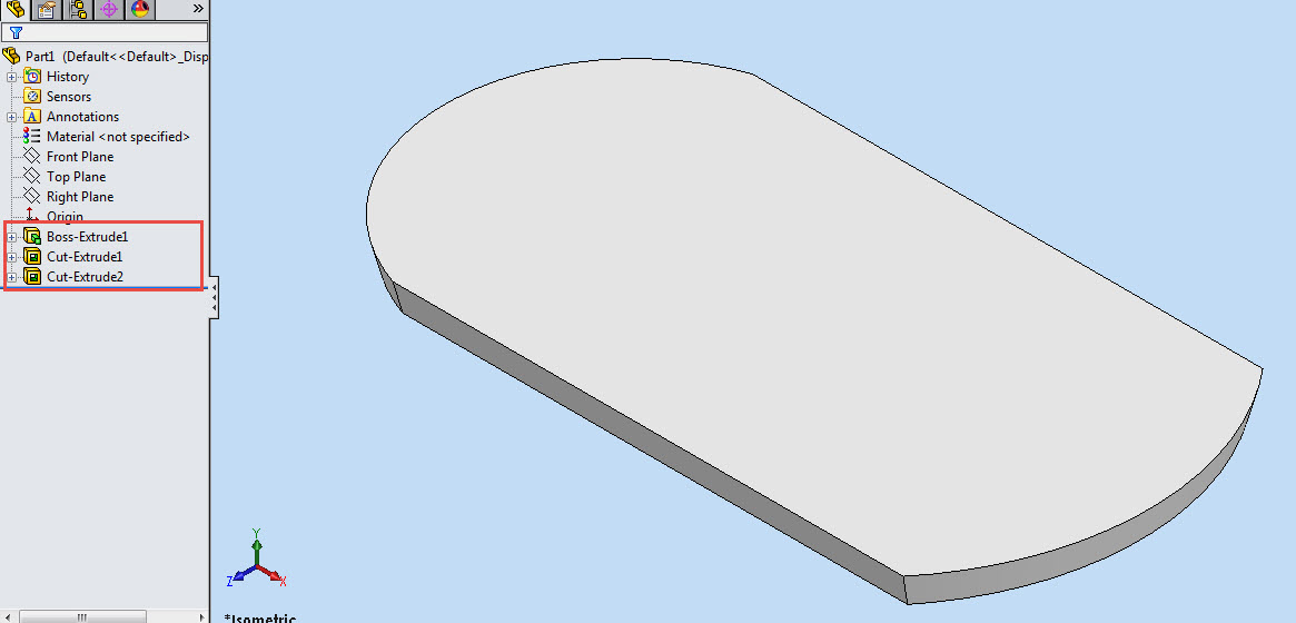
First part is quite simple after some basic sketching we will start our work using Extruded Boss/Base tool with a draft angle outward command. Then two extruded cut feature will be applied to complete the component.
First Component of Computer Mouse with SolidWorks
Then the first component will be placed in the assembly and the next component will be created in the context of first part. Later some sketches will be created on different planes and a Lofted Base/Boss feature will be used to form a sold. Then a Shell feature will be applied to hollow the part. Next some planes will be created, to be used as Trimming Surfaces in Split solid feature command. Then the model displayed will be trimmed according to the design requirement. This would convert the component in a multi body part.
This section of the tutorial displays the application of Split solid feature in a very professional manner . Later some Surfaces will also be created to be used as Trimming Surfaces in the aforesaid feature. In the end all the remaining bodies will be combined. Again some Extruded Cut feature will be applied to create holes for side buttons.

Second component of the assembly of computer mouse
From here a drastic change will occur in the modelling of this Computer Mouse. We will use configuration manager option of SolidWorks to create the next part to save time. Watch the tutorial to understand it more.

The remaining components are very common and I think there is no need to discuss them right now. Just watch everything in action the video is available below.


download-Link


Click the following link to get the model file: - http://bit.ly/2pFjUqE

Sunday, December 29, 2013

Application of Combine Tool (Join operation) Autodesk Inventor 2013

Application of Combine Tool (Join operation) Autodesk Inventor

Video Tutorial with caption and audio narration

In this video tutorial two pre-constructed parts have been utilized to show Boolean operation in a part file, by using 'Combine' tool that is available in the Modify panel of 3D Model tab.


First of all get the model files required to complete this tutorial by visiting the following link:- http://bit.ly/2oQSwpv 


Transcription of Video

1. We have two files one is Cylinder and the other is Example Insert.
2. Open the Cylinder file.
3. Activate the Derived Component tool.
4. Select the Example Insert file and open it.
5. Click OK to place the Example Insert in the design window.
6. Re-orient the model in the design window by using View Cube.
7. Change the Visual Style to Shaded with Hidden Edges to see the Example Insert clearly.
8. Two separate solid bodies are visible clearly in the Browser Bar.
9. Close the visibility of Cylinder.
10. Activate the Measure Tool from the Marking menu.
11. Take the measurement of this edge.
12. Measurement of the edge is 0.5 inch.
13. Open the visibility of Cylinder.
14. Start the Move Bodies tool.
15. And then select Example Insert.
16. Enter value 0 inch in the X Offset input box.
17. To move the Example Insert in Z direction.
18. Enter value (-0.5) inch in the Z Offset input box and click OK.
19. Activate the Combine tool.
20. Join option is selected by default.
21. Select both the solid bodies in the design window.
22. Click OK to close the dialog box.
23. Now checkout the Browser Bar, only one solid body exists.

Application of Combine Tool (Cut operation) Autodesk Inventor 2013

Application of Combine Tool (Cut operation)

Video Tutorial with caption and audio narration

In this video tutorial two pre-constructed parts have been utilized to show Boolean operation in a part file, by using 'Combine' tool that is available in the Modify panel of 3D Model tab.


First of all get the model files required to complete this tutorial by visiting the following link:- http://bit.ly/2ClzJpi 


Transcription of Video

1. We have two files one is Cylinder and the other is Example Insert.
2. Open the Cylinder file.
3. Activate the Derived Component tool.
4. Select the Example Insert file and open it.
5. Click OK to place the Example Insert in the design window.
6. Re-orient the model in the design window by using View Cube.
7. Two separate solid bodies are visible clearly in the Browser Bar.
8. Activate the Combine tool.
9. First select Cylinder as a base body.
10. And then select Example Insert as a tool body.
11. Join option is selected by default.
12. Select Cut option to remove the material from Cylinder Part.
13. Click OK to close the dialog box.