Serial No. 35
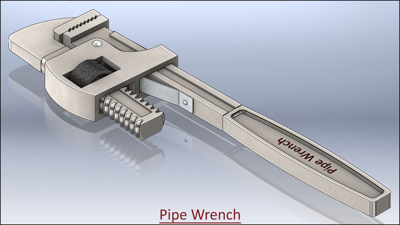
Animation displayed in 'Pipe Wrench' Assembly--SolidWorks 2014 (with caption and audio narration)
In this video, we will demonstrate how to apply the different type of mates in the assembly environment for creating the animation.
..................................................................................
To watch full sketching video of this model 'Pipe Wrench', please visit on my another associated video named as 'Pipe Wrench' (Video Tutorial) SolidWorks.

Click the following link to get the model file: - http://bit.ly/2VlqBK7
Transcription of the Video
- Create a new assembly inside an English template.
- The ‘Begin Assembly’ command is preactivated in the assembly design window.
- Go to the View tab and turn on the ‘Origins’ button.
- Place the ‘Part1’ file in the assembly.
- Turn off the visibility of ‘Origins’ button.
- Save the file call it as ‘Pipe Wrench with Animation’.
- When the first part file is placed in the assembly, the part remains as a grounded component.
- Activate the ‘Insert Components’ command and place the ‘Part2’ file in the assembly.
- Apply a ‘Concentric’ mate between the two holes of the Part.
- Apply a ‘Coincident’ mate between the Top Plane of ‘Part1’ and Top Plane of ‘Part2’.
- Apply an ‘Angle’ mate between these two edges of the parts.
- Fill the angle value 4.77 degrees in angle input box.
- Go to the View Cube and select the top view.
- Now you can examine here, how the angle mate works.
- Click OK to execute the command.
- Click the ‘Previous View’ button to return back to the Isometric view.
- Place the ‘Part5’ file in the assembly.
- Select the part file and precisely rotate it by using ‘Move with Triad’ command.
- Apply a ‘Concentric’ mate between inside cylindrical face of ‘Part5’ and hole of ‘Part2’.
- And choose ‘Lock Rotation’ option to check the movement of the part.
- Apply a ‘Coincident’ mate between the top face of ‘Part2’ and back face of ‘Part5’.
- Place the ‘Part6’ and ‘Part7’ file in the assembly.
- Apply a ‘Coincident’ mate between the top face of ‘Part7’ and side face of ‘Part1’.
- Apply a ‘Concentric’ mate between hole of ‘Part1’ and hole of ‘Part7’.
- Apply a ‘Coincident’ mate between the Top Plane of ‘Part1’ and Plane1 of ‘Part7’.
- Apply a ‘Concentric’ mate between the cylindrical face of ‘Part6’ and inner cylindrical face of hole of ‘Part7’.
- Apply a ‘Coincident’ mate between the side face of ‘Part7’ and back face of ‘Part6’.
- Place the ‘Part8’ file in the assembly.
- And rotate the part to a suitable position.
- Apply a ‘Concentric’ mate between holes of ‘Part8’ and ‘Part1’.
- Apply a ‘Coincident’ mate between the side face of ‘Part1’ and back face of the ‘Part8’.
- Apply a ‘Coincident’ mate between the Top Plane of ‘Part1’ and the Right Plane ‘Part8’.
- Place a copy of ‘Part6’ file in the assembly and mate it.
- Place the ‘Part3’ file and rotate in a proper position.
- Apply a ‘Coincident’ mate between the Top Plane of ‘Part2’ and Front Plane of ‘Part3’.
- Apply another ‘Coincident’ mate between the Top Plane of ‘Part3’ and Plane3 of ‘Part2’.
- Place the ‘Part4’ file in the assembly.
- Apply a ‘Coincident’ mate between the Plane2 of ‘Part2’ and the Right Plane of ‘Part4’.
- Go to the ‘Mechanical Mates’ tab in the Mate dialogue box.
- Different types of mechanical mates are available here, choose any mate as you need according to your design.
- Choose the ‘Screw’ mate button and select the ‘Distance/Revolution’ option.
- Set the ‘Distance/Revolution’ value 0.205 inches and choose ‘Reverse’ option.
- And apply the screw mate between Axis1 of ‘Part4’ and Axis1 of ‘Part3’.
- Click OK to finish the command.
- Drag the wheel of the wrench to check the screw mate and observe the result.
- The wheel rotates the jaw of Pipe Wrench with the help of ‘Screw’ mate command.
- Activate the ‘Move Component’ command and select the ‘Collision Detection’ option.
- Choose ‘These components’ option and select the ‘Part1’ and ‘Part3’ file.
- Make sure the ‘Stop at collision’ option should be selected.
- Activate the ‘Resume Drag’ button and drag the ‘Part3’ file until it touches to the opposite ‘Part1’ file.
- Now highlighted face shows here to stop the motion of the component at the moment of touch of any other entity.
- Click OK to finish the command.
- Apply a ‘Distance’ mate between the side face of ‘Part1’ and side face of ‘Part2’.
- The ‘Distance’ mate will automatically calculate the distance value of two components.
- Click OK to finish the command.
- Click on the ‘Motion Study’ tab and change the position of the model for creating the new view.
- Activate the ‘View Orientation’ command and select the ‘New View’ option.
- Set the ‘Named View’ as ‘View-1’ and click OK.
- Expand the animation timeline and go on the ‘Orientation and Camera’ tab.
- Right-click on the Orientation and Camera key, choose ‘Replace Key’ option.
- Now the Orientation and Camera key is replaced by changing from the ‘Isometric’ view to ‘View1’ with the help of ‘Replace Key’ command.
- Go to the ‘Distance2’ mate and move the timebar at 3 second.
- Copy the ‘Distance2’ mate key and paste it.
- Pause the animation for 3 seconds.
- Move the timebar at 33 second and double click on the distance mate to modify it.
- Fill the value (1.5831-1.00) inches in the Modify dialogue box and click OK.
- A new ‘Distance2’ key will be added at 33 second.
- Move the timebar at 53 second, copy above said key and paste it.
- A new ‘Distance2’ key will be added at 53 second.
- Move the timebar at 83 second, copy the ‘Distance2’ mate key and paste it.
- Go to the ‘Orientation and Camera Views’ tab.
- Copy the ‘Orientation and Camera Views’ key, whose name is ‘View-1’.
- Move the timebar at 38 second and paste the ‘View-1’ key.
- Move the timebar at 48 second and minimize the animation timeline.
- Go to the View Orientation toolbar and choose ‘Bottom View’.
- Right-click in the design window and go to the ‘Set Current View As’ option, select ‘Top’ view.
- Go to the View Orientation toolbar and choose back face of view cube.
- And set the current view as Front view.
- Go to the View Orientation toolbar and select this face, it will change into Isometric view.
- Activate the ‘New View’ and set the ‘Named View’ as ‘View-2’ and click OK.
- Expand the animation timeline and place the new key.
- The time consume 10 seconds in changing from View-1 to View-2 position.
- Copy the ‘View-2’ key and paste the key at 88 second.
- Move the timebar at 98 second, copy the ‘View1’ key and paste it.
- Move the timebar at 48 second and Right-click on the ‘Lights, Camera and Scene’ folder.
- Choose ‘Add Directional Light’ option.
- Now we will do some changes here in the basic light and light direction.
- Click OK to execute the command.
- The ‘Directional5’ light has been added to the Lights folder.
- Select the ‘Directional5’ light and activate the ‘Add/Update Key’ button.
- Now the light key is added at 48 second in the animation timeline by using ‘Add/Update Key’ command.
- In the same manner, add another light key at 38 second in the animation timeline.
- The time is being taken 10 seconds in changing from Default Light to ‘Directional5’ light to change the light direction of the model.
- Right-click on the ‘Directional5’ light and choose ‘Off in SolidWorks’ option.
- Copy the ‘Directional5’ light key and paste the key at 0 second.
- The Default light remains in still position for 38 seconds.
- In the same way, place two more ‘Directional5’ light keys at 88 second and 98 second in the animation timeline.
- Click ‘Calculate’ button and stop the animation.
- Clear the screen for a full view of the model and save the assembly.
- Play the animation.
- Stop the animation, here we have edited on the ‘View1’ position with the help of ‘Update Standards Views’ command.
- Expand the animation timeline, go on the ‘Orientation and Camera Views’ tab.
- Minimize the animation timeline and set position of the model.
- Right-click on the design window and activate the ‘Update Standards Views’ command and select ‘View1’ position.
- Go to the View Orientation tab and choose ‘View1’ position.
- Right-click on the ‘Custom’ view key and select ‘Replace Key’ option.
- In the same manner, update the two more view keys.
- At the last, click ‘Play from Start’ button to see the animation.