Showing posts with label Autodesk Inventor 2012 Video Tutorial. Show all posts

Wednesday, July 11, 2012

The Importance of Icons present in the Autodesk Inventor

Always focus on the Icons that are present everywhere in the software. For an example on the ribbon and on the dialogue boxes of tools etc. They are self-explanatory and give you information about how a tool will function. So watch every icon very carefully.
  For an example watch the dialogue box of the Mate Constraint too. To activate this tool just go to the Assembly tab>Position panel and click Constrain tool to activate it. Now the  Place Constraint dialogue box will open. The mate constraint is active and default solution type selected is mate. Focus on the solution section and see what the icon shows. Watch the image below.
Mate solution
  

  This Icon clearly states that mate constraint will work on entities that are in opposition to one another.


So when mating two components in an assembly always remember this. And where the red arrows show the opposite direction after selecting the planes, then the mate solution will work. Many a time the users think which mate solution, he should apply. So when red arrow shows the opposite direction then select mate and when the red arrows are showing like the Flush solution icon then select the flush solution. This is very helpful while working with a large assembly which consists of many components. To better understand it see the video below:-

Sunday, March 18, 2012

Applying Limits to a constraint (Autodesk Inventor 2012)


Applying Limits to a constraint (Autodesk Inventor 2012)
Constraint limits allow us to define minimum and maximum constraint values, so components can move freely within the limits but not beyond them. I am taking the very simple example of bucket model where I will apply limits to the angle constraint.

Monday, December 19, 2011

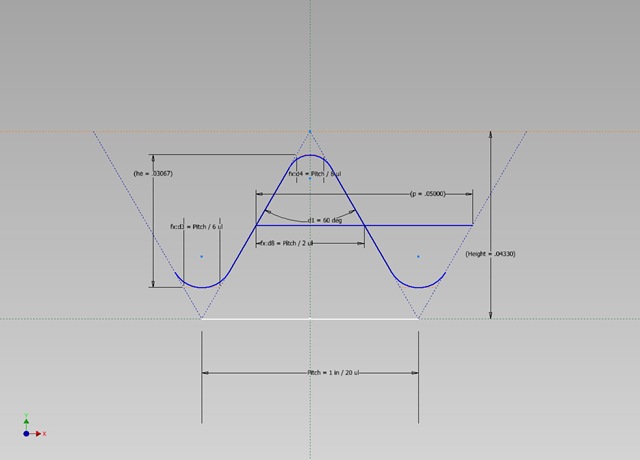
Unified and American screw internal thread profile- Autodesk Inventor 2012


Unified-and-American-screw-internal-thread Unified-and-American-screw-external-thread
 

In this video, I will show you how to create a thread profile for the Unified and American Screw thread (internal).With simple parameters and constraints we can create the sketch profile for this thread quite easily.

I did not applied detailed formula derived values in the beginning of sketch. But the final sketch proved the equations values itself.

The finished file is available for download for the Unified and American Screw internal and external both on the link below:--
http://bit.ly/2oOlPJg

Friday, December 16, 2011

Rectangular Pattern tool (Autodesk Inventor 2012)

Measuring-Scale-2 Measuring-Scale-1


Pattern tool is used to replicate sketch geometry. It is much faster than creating and dimensioning separate instances of the geometry. Main theme behind this video is to show how to divide a segment into equal parts. Autodesk Inventor sketching feature provides easy and convenient environment for designing these type of designs(simple or tuff).

HD Link for this video

The finished file link for the Measuring can be downloaded from the link below:--
http://mediafire.com/?2lvotbms6rqc32j

Wednesday, June 22, 2011

Creating and using a template file in Autodesk Inventor


In this video viewers will learn how to create and use  customized  template file in Autodesk Inventor. We are showing it in Autodesk Inventor 2012 but it is relevant for newer releases also.
To use customized template it is necessary to save it in the default template location. Default template location can be found in following way….
In Autodesk Inventor, click    Manage   Projects. Then expand the Folder Options node in the Project list. The Templates item shows location of Autodesk Inventor template files. If the location is [Default], place the cursor over the Templates item to display the path.

This video was created to reply a common question asked over youtube several time.
  • Question:What are My Preference .ipt  and My Preference .iam which you use during your file creation?
  • Answer: My Preference .ipt and My Preference .iam are template files that are used in Autodesk Inventor Software. I created it for my convenience. Anyone can create it easily after watching the video displayed here. You should set the Autodesk Inventor software according to you choice and save the template file. It will save your time and labour.

Monday, June 6, 2011

Thursday, May 12, 2011

Component Generators-Spur Gears (Autodesk Inventor 2012)


Component Generators-Spur Gears (Autodesk Inventor 2012)
With the help of Component Generators any type of gears can be created in Autodesk Inventor.
It is very useful feature of this software. Watch the video to know how it works.

Watch the following videos these are new addition:-


This video is inspired from the Skill Builders Examples available on the official web sight of Autodesk Inventor Software. To properly understand the Component Generator's Supur Gear function visit the following link:-
http://usa.autodesk.com/adsk/servlet/item?siteID=123112&id=10008317


This video is inspired from the Book Autodesk Inventor 2012 Essentials. Read the book to understand it more clearly.Visit the following link to know about the book:---
http://nisheeth-inventortalks.blogspot.in/p/other-learning-resources.html

This video is inspired from the Book Mastering Autodesk Inventor 2012. Read the book to understand it more clearly.Visit the following link to know about the book:---
http://nisheeth-inventortalks.blogspot.in/p/other-learning-resources.html