In this Siemens NX Tutorial, we will create the models of Engine Crankshaft and Camshaft Bushing. By watching this video viewer will observe as well as learn various part modelling techniques of Siemens NX software.
.................................................................................... The model designing concept is taken from videos available on YouTube. ....................................................................................
Hope all of you enjoyed the tutorial. If you find the video useful please like it and share it with your friends/colleagues and do not forget to subscribe me to get latest updates about my new uploads….
Dear Viewers if you like our work and wanted to support us, to keep continuing the good work, then become a patron of ours at ‘Patreon’ site. Patreon is a simple way for you to contribute to the creator’s work every month/ every time they release their new work and get rewards in return. Please visit the following link to know all about our work and what we are offering as the reward to our patrons…
In this Siemens NX Tutorial, we will create a model of Engine Camshaft Retainer. By watching this video viewer will observe as well as learn various part modelling techniques of Siemens NX software.
.................................................................................... The model designing concept is taken from videos available on YouTube. ....................................................................................
Hope all of you enjoyed the tutorial. If you find the video useful please like it and share it with your friends/colleagues and do not forget to subscribe me to get latest updates about my new uploads….
Dear Viewers if you like our work and wanted to support us, to keep continuing the good work, then become a patron of ours at ‘Patreon’ site. Patreon is a simple way for you to contribute to the creator’s work every month/ every time they release their new work and get rewards in return. Please visit the following link to know all about our work and what we are offering as the reward to our patrons…
In this Siemens NX Tutorial, we will create a model of Engine Valve Cover. By watching this video viewer will observe as well as learn various part modelling techniques of Siemens NX software.
.................................................................................... The model designing concept is taken from videos available on YouTube. ....................................................................................
Hope all of you enjoyed the tutorial. If you find the video useful please like it and share it with your friends/colleagues and do not forget to subscribe me to get latest updates about my new uploads….
Dear Viewers if you like our work and wanted to support us, to keep continuing the good work, then become a patron of ours at ‘Patreon’ site. Patreon is a simple way for you to contribute to the creator’s work every month/ every time they release their new work and get rewards in return. Please visit the following link to know all about our work and what we are offering as the reward to our patrons…
In this Siemens NX 11 Tutorial, we will create a model of Engine Oil Pan. By watching this video viewer will observe as well as learn various part modelling techniques of Siemens NX software.
.................................................................................... The model designing concept is taken from videos available on YouTube. ....................................................................................
Hope all of you enjoyed the tutorial. If you find the video useful please like it and share it with your friends/colleagues and do not forget to subscribe me to get latest updates about my new uploads….
Dear Viewers if you like our work and wanted to support us, to keep continuing the good work, then become a patron of ours at ‘Patreon’ site. Patreon is a simple way for you to contribute to the creator’s work every month/ every time they release their new work and get rewards in return. Please visit the following link to know all about our work and what we are offering as the reward to our patrons…
In this Siemens NX 11 Tutorial, we will create a model of Engine Side Cover. By watching this video viewer will observe as well as learn various part modelling techniques of Siemens NX software.
.................................................................................... The model designing concept is taken from videos available on YouTube. ....................................................................................
Hope all of you enjoyed the tutorial. If you find the video useful please like it and share it with your friends/colleagues and do not forget to subscribe me to get latest updates about my new uploads….
Dear Viewers if you like our work and wanted to support us, to keep continuing the good work, then become a patron of ours at ‘Patreon’ site. Patreon is a simple way for you to contribute to the creator’s work every month/ every time they release their new work and get rewards in return. Please visit the following link to know all about our work and what we are offering as the reward to our patrons…
In this Siemens NX 11 Tutorial, we will create a model of Engine Belt Wheel. By watching this video viewer will observe as well as learn various part modelling techniques of Siemens NX software.
.................................................................................... The model designing concept is taken from videos available on YouTube. ....................................................................................
Hope all of you enjoyed the tutorial. If you find the video useful please like it and share it with your friends/colleagues and do not forget to subscribe me to get latest updates about my new uploads….
Dear Viewers if you like our work and wanted to support us, to keep continuing the good work, then become a patron of ours at ‘Patreon’ site. Patreon is a simple way for you to contribute to the creator’s work every month/ every time they release their new work and get rewards in return. Please visit the following link to know all about our work and what we are offering as the reward to our patrons…
In this Siemens NX 11 Tutorial, we will create a model of Camshaft. By watching this video viewer will observe as well as learn various part modelling techniques of Siemens NX software. The highlight of the tutorial is that we will learn how to create a Non-associative pattern so that we can modify patterned geometries using Move Object tool without affecting others. .................................................................................... The model designing concept is taken from videos available on YouTube. ....................................................................................
Hope all of you enjoyed the tutorial. If you find the video useful please like it and share it with your friends/colleagues and do not forget to subscribe me to get latest updates about my new uploads….
Dear Viewers if you like our work and wanted to support us, to keep continuing the good work, then become a patron of ours at ‘Patreon’ site. Patreon is a simple way for you to contribute to the creator’s work every month/ every time they release their new work and get rewards in return. Please visit the following link to know all about our work and what we are offering as the reward to our patrons…
In this Siemens NX 11 Tutorial, we will create a model of Engine Air Filter. By watching this video viewer will observe as well as learn various part modelling techniques of Siemens NX software. .................................................................................... The model designing concept is taken from videos available on YouTube. ....................................................................................
Hope all of you enjoyed the tutorial. If you find the video useful please like it and share it with your friends/colleagues and do not forget to subscribe me to get latest updates about my new uploads…. http://www.youtube.com/user/nisheethsorjm?sub_confirmation=1 ....................................................................................................
Dear Viewers if you like our work and wanted to support us, to keep continuing the good work, then become a patron of ours at ‘Patreon’ site. Patreon is a simple way for you to contribute to the creator’s work every month/ every time they release their new work and get rewards in return. Please visit the following link to know all about our work and what we are offering as the reward to our patrons…
In this Siemens NX 11 Tutorial, we will create a model of Engine Exhaust Manifold and its mirror part by using Wave Linker Function of the software. By watching this video viewer will observe as well as learn various part modelling techniques of Siemens NX software. The application of Through Curve Mesh Tool has been displayed in the video in quite a detail that is the highlight of the video. .................................................................................... The model designing concept is taken from videos available on YouTube. ....................................................................................
Hope all of you enjoyed the tutorial. If you find the video useful please like it and share it with your friends/colleagues and do not forget to subscribe me to get latest updates about my new uploads….
Dear Viewers if you like our work and wanted to support us, to keep continuing the good work, then become a patron of ours at ‘Patreon’ site. Patreon is a simple way for you to contribute to the creator’s work every month/ every time they release their new work and get rewards in return. Please visit the following link to know all about our work and what we are offering as the reward to our patrons…
In this Siemens NX 11 Tutorial, we will create a model of Engine Cylinder Head. By watching this video viewer will observe as well as learn various part modelling techniques of Siemens NX software. .................................................................................... The model designing concept is taken from videos available on YouTube. ....................................................................................
Hope all of you enjoyed the tutorial. If you find the video useful please like it and share it with your friends/colleagues and do not forget to subscribe me to get latest updates about my new uploads…. http://www.youtube.com/user/nisheethsorjm?sub_confirmation=1 ....................................................................................................
Dear Viewers if you like our work and wanted to support us, to keep continuing the good work, then become a patron of ours at ‘Patreon’ site. Patreon is a simple way for you to contribute to the creator’s work every month/ every time they release their new work and get rewards in return. Please visit the following link to know all about our work and what we are offering as the reward to our patrons…
In this Siemens NX 11 Tutorial, we will create an assembly of Rocker Arm which is a component of Engine. While creating this model we will observe as well as learn various part and assembly modelling techniques of Siemens NX software. First components of assembly named Rocker Arm Pin_1 & 2, Rocker Arm Roll and Rocker Arm and later with the help of them the final assembly will be created. .................................................................................... The model designing concept is taken from videos available on YouTube. ....................................................................................
.................................................................................... Visit the following link to watch more tutorial on Siemens NX by us
Hope all of you enjoyed the tutorial. If you find the video useful please like it and share it with you friends/colleagues and do not forget to subscribe me to get latest updates about my new uploads….
Dear Viewers if you like our work and wanted to support us, in keep continuing the good work, then become a patron of ours at ‘Patreon’ site. Patreon is a simple way for you to contribute to creator’s work every month/ every time they release their new work and get rewards in return. Please visit following link to know all about our work and what we are offering as reward to our patrons…
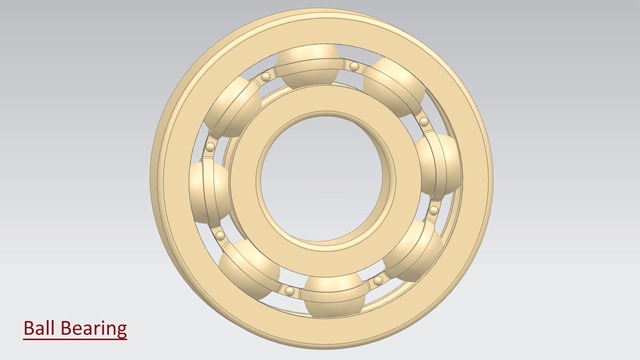
In this Siemens NX 11 Tutorial, we will create a model of Ball Bearing. First of all components of Ball Bearing — Outer ring, Inner ring, Cage, Rivet and Ball will be created. With the help of these components final assembly will be created. So viewers will be able to observe and learn part and assembly modelling techniques.
Hope all of you enjoyed the tutorial. If you find the video useful please like it and share it with your friends/colleagues and do not forget to subscribe me to get latest updates about my new uploads….
Dear Viewers if you like our work and wanted to support us, in keep continuing the good work, then become a patron of ours at ‘Patreon’ site. Patreon is a simple way for you to contribute to creator’s work every month/ every time they release their new work and get rewards in return. Please visit following link to know all about our work and what we are offering as a reward to our patrons…
In this Siemens NX 11 Tutorial, we will create a model of Engine Block which is a component of an Engine Assembly. By watching this tutorial viewers will be able to observe and learn various 2D sketching techniques, application of Extrude, Rib, Mirror, Unite, Pattern, Fillet etc. Tools.
Hope all of you enjoyed the tutorial. If you find the video useful please like it and share it with you friends/colleagues and do not forget to subscribe me to get latest updates about my new uploads….
Dear Viewers if you like our work and wanted to support us, in keep continuing the good work, then become a patron of ours at ‘Patreon’ site. Patreon is a simple way for you to contribute to creator’s work every month/ every time they release their new work and get rewards in return. Please visit following link to know all about our work and what we are offering as reward to our patrons…
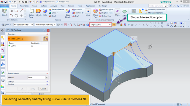
In this Siemens Nx 11 tutorial we will learn how to smartly use Curve Rule command available to define fewer number of selections while using many NX tools. We will also observe Stop at intersection option which is used in combination with the Curve Rule setting that lets you specify which portions of the section curves to use.
Video Transcription
Here are some sketches drawn on different Datum Planes which means these all are not connected at all. With the help of these, we need to create a closed surface.
Activate Fill Surface Tool.
Before Selecting Curves, we will examine different options listed in Curve Rule dialogue box.
We can choose Region Boundary curve by which we can select a region surrounded by a connected curve. The same can be done by 'Connected Curves' option.
Now see how 'Single Curve' option can be used here.
Here we need to select a specific portion of the curve, so activate Stop at intersection option to get the desired result.
Now we are able to easily select a specific portion of the curves.
Visit following link to get related finished tutorial file..
.................................................................................... Visit the following link to watch more tutorial on Siemens NX by us https://www.youtube.com/playlist?list=PLKWX3xUP3pPpUvtPuzEPoHimjTjpdbl_Q ......................................................................... Hope all of you enjoyed the tutorial. If you find the video useful please like it and share it with you friends/colleagues and do not forget to subscribe me to get latest updates about my new uploads…. http://www.youtube.com/user/nisheethsorjm?sub_confirmation=1 .................................................................................................... Dear Viewers if you like our work and wanted to support us, in keep continuing the good work, then become a patron of ours at ‘Patreon’ site. Patreon is a simple way for you to contribute to creator’s work every month/ every time they release their new work and get rewards in return. Please visit following link to know all about our work and what we are offering as reward to our patrons… https://www.patreon.com/nisheethsri
Hello viewers in this tutorial, we are going to create a bolt and nut of ½ inch dia where we will create threads manually using a Unified National Fine (UNF) Thread profile of 1/20 inch pitch. We will create using equations so that by changing the dia, length and pitch the size of bolt and nut can be modified. To show how it can be done we will also create a bolt of 3/8 inch dia having a pitch of 1/24 inches by changing the parameters using the expression command. In a previous tutorial, we demonstrated how to create UNF Thread Profile.
Video Transcription
Start a new model file using inch units.
Fill the name of the file Bolt.
Switch to ‘Tools Tab’ and activate ‘Expressions’ command.
Create a new expression named D and fill ½ inches in Formula, click ok to exit from the command.
Start a new sketch over YZ plane.
First set some preferences of the software.
Here in Drafting Preference in the Text Units under Dimension settings, set the decimal places of units to 5 and ‘Decimal Delimiter’ to the period instead of a comma.
Draw a polygon and apply a vertical constraint on its this side.
Apply a dimension of D*1.5 over here on this polygon and exit from the sketching mode.
Extrude this sketch profile and in ‘End Distance’ field fill value D*0.634.
Change the colour of the model using ‘Edit Object Display command available at ‘View Tab’.
Edit the colour of the model and apply a custom colour by filling the values 247 in Red, 225 in Green and 182 in Blue input dialogue box.
Create a new sketch over XZ plane of the model and draw a sketch using ‘Line Tool’ as displayed.
Apply a dimension of D*1/8 over this line and an angle of 30° between both lines.
The sketch is complete so revolve it and remove the material from the solid.
Create a sketch, over this face of the model and activate Static Wireframe view mode.
Draw a circle coincident to the origin of the model.
Apply a tangent constraint between the circle and this edge of the model.
Re-activate ‘Shaded with Edges’ view mode.
Create another circle in the sketch and apply an offset dimension of D*1/16 between these circles.
Convert this circle into reference geometry and exit from the sketching mode.
Extrude this sketch and in Extrude dialogue box fill the ‘End Distance’ 1/64 and in offset option select Two-Sided.
In offset distance at end value box, fill 0.25 inches and execute the command after reversing the direction of Extrude.
Create a new sketch over following face of the model and draw a circle coincident with the sketch origin next apply a dimension D here.
Exit from the sketching mode and Extrude this sketch up to 2 inches.
Hide the visible of sketches and save the file.
Apply a chamfer over the following edge of the model, having 1/32 inches of length and 45 degrees of angle.
Create a new sketch over XZ plane.
Activate Intersection Curve command and select following face of the model.
Here you can see in selection filter Curve option is selected which means while making a selection only sketch curves will be selected.
Select all the curve present in the sketch and convert them into reference geometry.
Draw two reference lines in the sketch as displayed and exit from the sketching mode.
Next, open the folder named UNF Screw Thread Profiles from your hard drive. Check the video description and Youtube Cards to find the files required to complete this tutorial.
From here open file named ‘UNF Screw External Thread Profile’.
Here edit sketch which is visible in front of you.
Select these arcs and lines.
Activate copy command from the right-click menu to copy the selected sketches to the clipboard.
Exit from the sketch and switch back to Bolt file.
Edit the last sketch we created and paste the sketch which is present in the windows clipboard.
Activate ‘Profile Tool’ and add these lines to the profile so that it clearly intersect the solid created up till now in the file.
Select the thread profile sketch after activating sketch filter as a curve.
Activate Move Curve tool.
First, verify that ‘Angle’ is selected in ‘Transform Motion’ type.
Next, specify Axis Point as displayed.
Then fill 180° and click apply.
Now in Transform Motion type select Point to Point.
First, specify ‘from’ point and then specify ‘to’ point as displayed.
Select sketches to be moved and click ok.
Exit from the sketching mode.
Switch to Analysis Tab and activate Measure Distance Command.
Measure the total length of the bolt as displayed, that is 2.3170 inch.
Activate Helix Cure Tool from Curve Tab.
In the X, Y, Z coordinate position of the curve, fill the last measured distance 2.3170 inches in X input field and rotate the curve by -90°.
The diameter of the curve should be 0.5 inches, in pitch fill the value 1/20+0.001 and length of the curve should be 1.25 inches.
In the start angle, fill a value so that start point of curve coincident with the UNF thread profile.
Activate Swept Tool and first select the thread profile, next Helix curve as guides.
Verify that ‘Orientation Method’ is selected as ‘Vector Direction’ and then define vector direction as displayed.
Click Ok to execute the command.
Hide the visibility of sketches and curves.
Activate Subtract Tool, select bolt as target body and swept feature as a tool body.
Execute the command and threads are created in front of us.
Hide everything in the file except solid bodies.
The file is complete so save it.
Let us see how we can change the size of the bolt by changing some parameters using references command.
We will change the dia of the bolt to 3/8 inches and pitch of threads to 1/24 inches.
First, suppress Swept and Subtract feature because these features will not update automatically after changing the parameters.
Activate Expressions command and change the value of D to 3/8 inches.
All the formula values depending on this parameter will update automatically.
Edit the Extrude (8) feature and change the End distance value to 1.5 inches.
Open the UNF Screw External Thread Profile file and change the value of pitch to 1/24 from Expressions table.
The whole sketch will update accordingly.
Copy the sketch to the windows clipboard as we did earlier and switch back to bolt file.
Edit the sketch where we placed the UNF thread profile earlier.
First, delete the existing sketch and then paste the modified sketch.
Do the same procedure as we did earlier to place the sketch at the appropriate position and exit from the sketching mode.
Measure the total length of the bolt which is now 1.7377 inches.
Edit the helix curve.
In the X input field fill the measured value 1.7377 inches.
Change the diameter of helix curve to 3/8, Pitch to 1/24+0.001 and length to 1 inches.
Open the visibility of helix curve.
Now delete the Swept feature and Subtract feature will delete automatically.
Activate Swept tool and select UNF thread profile and helix curve as guides.
Activate preserve shape option and specify Vector Direction as displayed.
Click OK to execute the command.
Next, subtract solid created by the swept feature from the bolt.
The tool is not selecting the swept feature which means there is some problem with it so we will correct it.
Edit the swept feature, here see the thread profile has not been selected properly.
Select this arc which was missing.
In body type select ‘Solid’ instead of a ‘Sheet’ and click ok.
Now re-apply Subtract Command and it will work properly.
Now we have modified the bolt successfully so save it with a different name.
This is ½ dia inch bolt and this is 3/8 inch dia bolt.
Now switch to ½ inch dia bolt and save as the file with the name nut.
In this file, we will make some changes to create nut model which will save our time.
Select all the features after the Revolve (4) and delete it.
Edit this Sketch (1) and edit this dimension, change its value to D*(1+5/8) and exit the sketch.
This change also reflects in Expressions Table.
Next, we need to create a hole.
To determine it’s dia we will check ANSI Internal Screw Threads Chart.
Our screw size is ½ -20 so it’s minimum Minor Diameter is 0.4460 inches which we will use in creating a hole.
Turn on the visibility of coordinate System from Show and Hide command available at the View Tab.
Activate ‘Hole’ command and first define the position of the hole as the model origin.
Fill the diameter of the hole which we got from the ANSI Internal Screw Threads Chart that is 0.4460 inches and in depth limit select Through Body option.
Click ok to execute the command.
Edit the extrude length value to D*0.884 inches.
Apply a chamfer of 1/32 inches distance and 45° angles on the following edge.
Create a new sketch over XZ plane.
Activate Intersection Curve command and select following face of the model.
Draw two more lines and convert all lines in the sketch into reference geometry.
Exit the sketch and open the file of UNF Screw Internal Thread Profile.
Copy the sketch from the file as we did earlier and switch back to the Nut file.
Edit the last sketch we created and paste the copied sketch here.
Add few more lines to close the profile and move it to the appropriate position.
Exit the sketch and activate the Helix Curve tool.
In the helix X, Y, Z co-ordinate fill the value of X to 0.442 + 0.00625 and rotate it to position the curve properly.
Fill the value -180° in angle, 0.446 inches in diameter, 0.051 inches in pitch and 0.5 inches in length input box.
Click Ok to create the Helix Curve.
Activate Swept Tool and select the thread profile then select Helix curve as a guide.
Specify vector direction and click ok.
Subtract solid created with the swept tool from the main body to create threads.
Hide everything in the file except solid bodies.
Activate Clip Section view to examine the threads.
Exit from the section view and save the file.
Close this file and create a new assembly file named Bolt and Nut using inch units.
First, add Bolt component in the assembly.
Placement of the bolt will be at the absolute origin in reference to the entire part.
Apply ‘Fix’ Assembly Constraint over it.
Hide sketches and curves in the file.
Change colour of the model as displayed.
Now add Nut component in the assembly.
Set the placement of the model to move.
Drag the component to the appropriate position.
Hide everything except solid in the file.
Edit the Bolt component and open the visibility of Datum Coordinates of it.
Do the same for Nut component.
Align axis of Bolt and Nut using Touch Align Constraint.
Hope all of you enjoyed the tutorial. If you find the video useful please like it and share it with your friends/colleagues and do not forget to subscribe me to get latest updates about my new uploads….
Dear Viewers if you like our work and wanted to support us, in keep continuing the good work, then become a patron of ours at ‘Patreon’ site. Patreon is a simple way for you to contribute to creator’s work every month/ every time they release their new work and get rewards in return. Please visit the following the link to know all about our work and what we are offering as a reward to our patrons…
Hello viewers in this tutorial, we are going to create a Unified National Fine (UNF) Thread profile in Siemens Nx software. External and Internal profiles will be created separately. That would be used in creating Bolt and Nut which will be demonstrated later in another video.
Video Transcription
Start a new file using inch units.
Fill the name of the file UNF Screw External Thread Profile.
Create a new sketch over XZ plane.
Before starting the sketch we will set some preferences of the software.
Here in Drafting Preference under the text, set the decimal places of units to 5 and ‘Decimal Delimiter’ to the period instead of a comma.
Create a line and apply a dimension of 1/20 inches to it.
Apply a coincident constraint between the midpoint of this line and sketch origin.
Switch to Tools Tab and click over the ‘Expression’ command, here you can see the last dimension we applied over the line, named p0, change its name to Pitch which will be used as constant later.
Convert this line to a reference line.
Create two more lines in the sketch and apply a 60° angle between them.
We can see a vertical constraint has been automatically applied by the software between the intersection of newly created two lines and sketch origin.
Convert these two lines into reference line.
Create two more lines parallel to the previous lines as shown here.
Apply between horizontal constraints between the endpoints of these lines and convert them into reference lines.
Create another reference line and apply a horizontal constraint over it.
Apply a dimension of Pitch/6 over it.
In the same way, create another reference line collinear to the previous line on the other side.
Next add another reference line over here and apply a dimension of Pitch/8 over it.
Activate Arc tool and draw an arc tangent to these three lines and apply constraints as required.
Next, draw another arc coincident to the midpoint of this line and tangent to the adjacent line by applying constraints.
Mirror this arc to the other side using Mirror Curve tool.
Connect these arcs using lines to complete the sketch which we require.
Here we can see an auto dimension is still applied which means something is missing.
Fully constrain the sketch by applying a horizontal constraint over this line.
The sketch is complete so exit the sketch and save it.
Addition to this we need to create another Thread Profile for the Internal screw too, to do so, save as, this file with the name ‘UNF Screw Internal Thread’ Profile.
So we can see the file saved as for Internal Thread Profile is currently active next make some changes in the sketches.
Delete these sketches.
Change the value of this dimension to Pich/4.
Draw these lines using Profile Tool as shown.
Here apply a coincident constraint between the endpoints of the line which was not created automatically.
See the sketch is now fully constrained.
Chang back this reference line into normal line.
Our sketch is complete so exit from the sketching mode.
Hope all of you enjoyed the tutorial. If you find the video useful please like it and share it with your friends/colleagues and do not forget to subscribe me to get latest updates about my new uploads….
In this tutorial, we will show the way to use Pattern Geometry Tool to create a nonassociative pattern so that we can modify patterned geometries without affecting parent feature. Addition to this application of Move Object tool is also displayed.
.................................................................................................... Followig video demonstrates the full modeling process of Crankshaft model…....
....................................................................................
Visit the following link to watch more tutorial on Siemens NX by us https://www.youtube.com/playlist?list=PLKWX3xUP3pPpUvtPuzEPoHimjTjpdbl_Q .........................................................................
Hope all of you enjoyed the tutorial. If you find the video useful please like it and share it with you friends/colleagues and do not forget to subscribe me to get latest updates about my new uploads…. http://www.youtube.com/user/nisheethsorjm?sub_confirmation=1
In this Siemens Nx tutorial, we will learn about modelling a ‘Piston’ Assembly. The model has four components which will be created individually later all of them placed into the assembly. So viewers will be able to watch part modelling as well as assembly modelling techniques of ‘Siemens Nx’ software. .................................................................................... The model designing concept is taken from videos available on YouTube. ....................................................................................
.................................................................................... Visit the following link to watch more tutorial on Siemens Nx by us https://www.youtube.com/playlist?list=PLKWX3xUP3pPpUvtPuzEPoHimjTjpdbl_Q .........................................................................
Hope all of you enjoyed the tutorial. If you find the video useful please like it and share it with you friends/colleagues and do not forget to subscribe me to get latest updates about my new uploads….
In this Siemens NX 10 Tutorial, we will create a model of Crankshaft. While creating this model we will learn how to create a Non-associative pattern so that we can modify patterned geometries without affecting others. To do so we will use Pattern Geometry and Move Object tool. Addition to this application of many 2D sketching, Extrude and Fillet Tools are also displayed.
Hope all of you enjoyed the tutorial. If you find the video useful please like it and share it with you friends/colleagues and do not forget to subscribe me to get latest updates about my new uploads….
In this Siemens NX 10 Tutorial we will create a Chuck and Key Assembly. First we will create Chuck and Key parts and then assemble it. So viewers will learn following Part and Assembly Modeling topics:--
Part Modeling
1. Creating a new model file with specified units.
2. Basic Sketching
3. Extrude Tool
4. Revolve Tool
5. Swept Tool
6. Move Face
7. Trim Body
8. Pattern Tool
9. Hole Tool
10. Chamfer.
Assembly Modeling
1. Creating new assembly file with specified units.
Hope all of you enjoyed the tutorial. If you find the video useful please like it and share it with you friends/colleagues and do not forget to subscribe me to get latest updates about my new uploads….