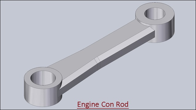
The Design of ‘Engine Connecting Rod’ has been taken from Assembly file of 'Rear Exhaust-2 Shoe' of ‘Sample files’ of Autodesk Inventor, it is a fragment of ‘Engine MKII’ Assembly. Rest components of the model ‘Engine MKII Assembly’ (consisting of several numbers) have also been designed. You may watch them by visiting on the following playlist:- https://www.youtube.com/playlist?list=PLKWX3xUP3pPrb1bU6P_goEUCMvcfTuqtI ....................................................................................... Inside this video, you can see the full detailed process of making 3-D Parametric CAD Model through Solid Edge ST9.
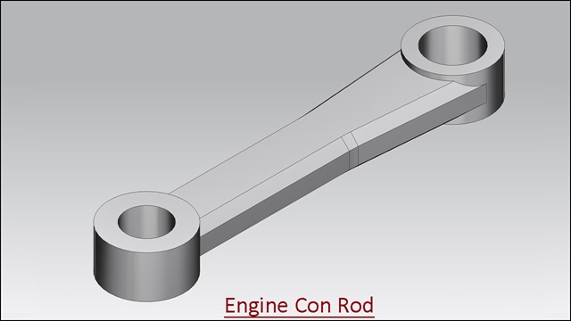
The Design of ‘Engine Connecting Rod’ has been taken from Assembly file of 'Rear Exhaust-2 Shoe' of ‘Sample files’ of Autodesk Inventor, it is a fragment of ‘Engine MKII’ Assembly. Rest components of the model ‘Engine MKII Assembly’ (consisting of several numbers) have also been designed. You may watch them by visiting on the following playlist:- https://www.youtube.com/playlist?list=PLKWX3xUP3pPplOPikb5S8WD4re7tAnT3- ....................................................................................... Inside this video, you can see the full detailed process of making 3-D Parametric CAD Model through Siemens NX 11.
Create sketches with the help of Circle tool, Center Point Arc tool, and Line tool.
Use Add Relations and dimensions to fully defined the sketches as displayed.
The sketch is complete so exit from the sketching mode.
Activate the ‘Extruded Boss/Base’ tool and select a sketch profile to create a solid feature.
Enter the value in the Depth field for Direction 1 to define the depth of the model.
Click Reverse Direction button to extend the feature in the opposite direction from that shown in the preview.
Save the part file with the name ‘Engine Con Rod’.
Change the colour of model to Polished Steel.
Next create another sketch over the top face of the model and create another Extrude feature as displayed.
If you want to create a new work plane on the middle of the part, activate the Plane tool and select top face of part and bottom face of part a plane is automatically created on the middle of the part.
Mirror of Boss-Extrude2 feature on the basis of Plane1 by using 'Mirror' tool.
Add Fillet and Chamfer features to complete the model.
Take project of X&Y Axis by using ‘Project Geometry’ tool.
Create sketches with the help of Circle tool, Centre Point Arc tool and Line tool.
Use sketch constraints and dimensions to full define the sketch as displayed.
The sketch is complete so exit from the sketching mode.
Activate the Extrude command first select the sketch profile next fill the value in the under the Extents field to define the depth of model. You can see type of Extent is selected as Distance automatically.
Save the part file with the name ‘Engine Con Rod’.
Next create another sketch over the top face of the model and create another Extrude feature as displayed.
If you want to create a new work plane on the middle of the part, activate the Plane tool and select top face of part and bottom face of part a plane is automatically created on the middle of the part.
Mirror of Extrusion2 feature on the basis of Work Plane1 by using 'Mirror' tool.
Add Fillet and Chamfer features to complete the model.