Showing posts with label Rod. Show all posts

Friday, April 8, 2022

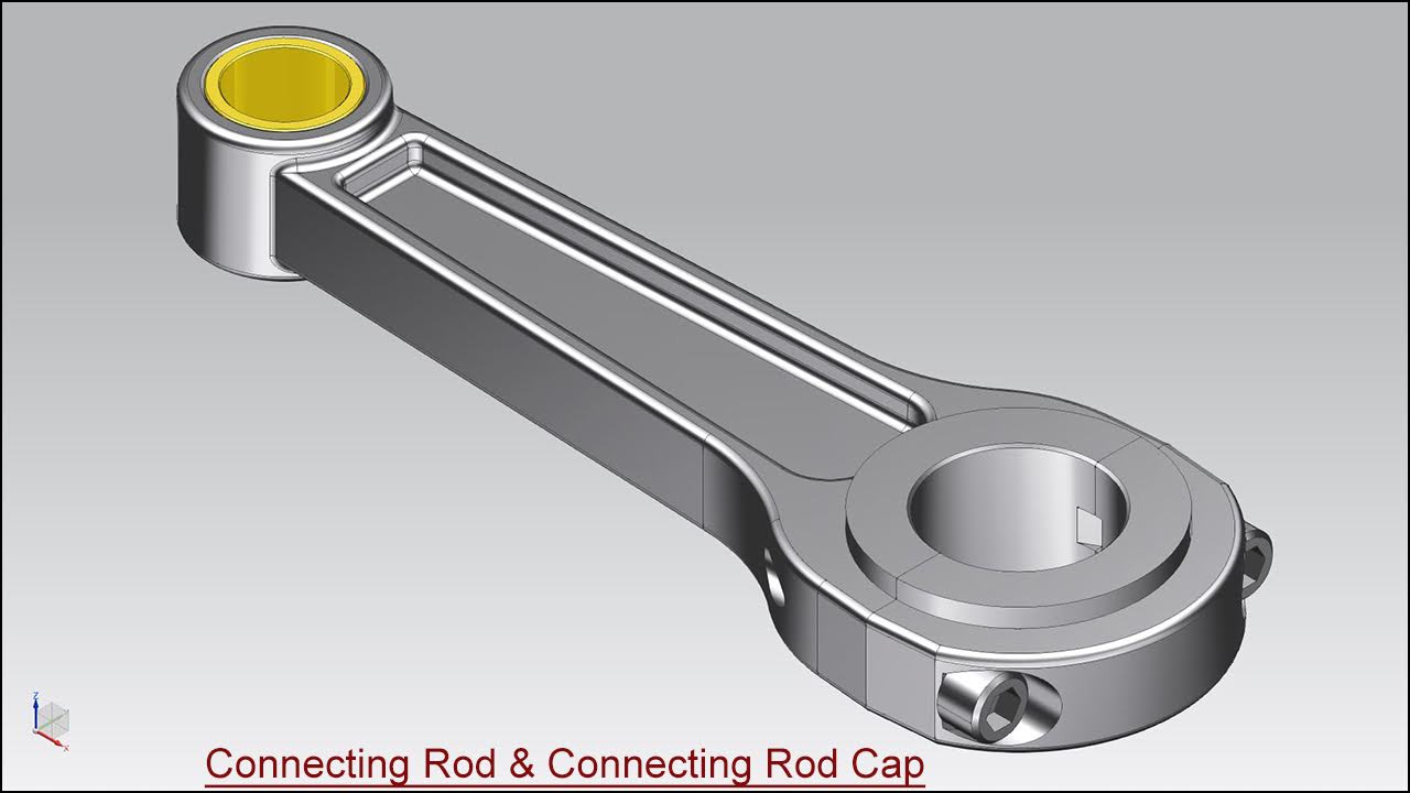
Connecting Rod and Connecting Rod Cap Assembly (Siemens NX 1855 Tutorial)

Serial No. 146

Connecting Rod and Connecting Rod Cap Assembly (Siemens NX 1855 Tutorial)

In this Siemens NX 1855 Assembly tutorial, we have created a model named ‘Connecting Rod and Connecting Rod Cap’. In this video, you will learn the full modelling process of this model and its components. This assembly consists of 2 part files and 1 Bolt to make this assembly that is positioned according to design intent by using Assembly Constraints like Touch/Align Constraint, Infer Centre Axis Constraints etc. You will learn how to create basic 2D sketches on different Datum planes as well as Extrude, Revolve, Chamfer, Edge Blend, Unite, Swept tools and create simple/counterbore holes by using the 'Hole' command and create two new solid bodies within one part file by using the under the Revolve tool.


Click the following link to get the model file: - https://bit.ly/3jhb235


......................................................................
Visit the following link to watch more tutorial on Siemens NX by us
https://www.youtube.com/playlist?list=PLKWX3xUP3pPpUvtPuzEPoHimjTjpdbl_Q
.........................................................................
Hope all of you enjoyed the tutorial. If you find the video useful please like it and share it with your friends/colleagues and do not forget to subscribe me to get latest updates about my new uploads….
http://www.youtube.com/user/nisheethsorjm?sub_confirmation=1
....................................................................................................
Dear Viewers if you like our work and wanted to support us, to keep continuing the good work, then become a patron of ours at ‘Patreon’ site. Patreon is a simple way for you to contribute to the creator’s work every month/ every time they release their new work and get rewards in return. Please visit the following link to know all about our work and what we are offering as the reward to our patrons…
https://www.patreon.com/nisheethsri
...............................................................…   

Saturday, June 17, 2017

Engine Connecting Rod (Solid Edge ST9 Tutorial)

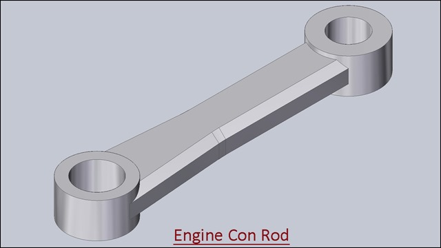
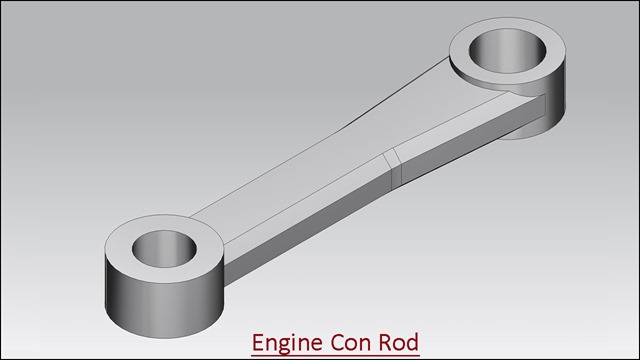
Engine Con Rod

Serial No. 78

Engine Connecting Rod (Solid Edge ST9 Tutorial)

The Design of ‘Engine Connecting Rod’ has been taken from Assembly file of 'Rear Exhaust-2 Shoe' of ‘Sample files’ of Autodesk Inventor, it is a fragment of ‘Engine MKII’ Assembly.
Rest components of the model ‘Engine MKII Assembly’ (consisting of several numbers) have also been designed. You may watch them by visiting on the following playlist:-
https://www.youtube.com/playlist?list=PLKWX3xUP3pPrb1bU6P_goEUCMvcfTuqtI
.......................................................................................
Inside this video, you can see the full detailed process of making 3-D Parametric CAD Model through Solid Edge ST9.

download-Link


Click the following link to get the model file: - http://bit.ly/2OxgP6k

Engine Connecting Rod (Siemens NX 11 Tutorial)

Engine Con Rod

Serial No. 74

Engine Connecting Rod (Siemens NX 11 Tutorial)

The Design of ‘Engine Connecting Rod’ has been taken from Assembly file of 'Rear Exhaust-2 Shoe' of ‘Sample files’ of Autodesk Inventor, it is a fragment of ‘Engine MKII’ Assembly.
Rest components of the model ‘Engine MKII Assembly’ (consisting of several numbers) have also been designed. You may watch them by visiting on the following playlist:-
https://www.youtube.com/playlist?list=PLKWX3xUP3pPplOPikb5S8WD4re7tAnT3-
.......................................................................................
Inside this video, you can see the full detailed process of making 3-D Parametric CAD Model through Siemens NX 11.

download-Link


Click the following link to get the model file: - http://bit.ly/2OyOcWB

Saturday, August 15, 2015

Engine Connecting Rod (SolidWorks 2015 Tutorial with Caption)


Engine Con Rod_1

Engine Con Rod_2


Serial No. 152

Engine Connecting Rod (SolidWorks 2015 Tutorial with Caption)

In this SolidWorks tutorial we will create an Engine Con Rod. It is a part modeling tutorial that will cover following topics: ---

· Creating some 2Dsketches with the basis of different planes.

· Understand the sketch constraints and dimensions to works effectively.

· How to establish the relationship between geometry.

· How to create a work plane on middle of the part.

· How to use Mirror tool on the basis of plane.

· How to use Extrude Base/Boss tool, Fillet tool, Chamfer tool etc.
 

download-Link

Click the following link to get the model file: -http://bit.ly/359YTEQ


Transcription of the Video:-

  1. Create a new Part file.

  2. Create a new sketch over Top Plane.

  3. Draw the vertical/horizontal construction lines.

  4. Create sketches with the help of Circle tool, Center Point Arc tool, and Line tool.

  5. Use Add Relations and dimensions to fully defined the sketches as displayed.

  6. The sketch is complete so exit from the sketching mode.

  7. Activate the ‘Extruded Boss/Base’ tool and select a sketch profile to create a solid feature.

  8. Enter the value in the Depth field for Direction 1 to define the depth of the model.

  9. Click Reverse Direction button to extend the feature in the opposite direction from that shown in the preview.

  10. Save the part file with the name ‘Engine Con Rod’.

  11. Change the colour of model to Polished Steel.

  12. Next create another sketch over the top face of the model and create another Extrude feature as displayed.

  13. If you want to create a new work plane on the middle of the part, activate the Plane tool and select top face of part and bottom face of part a plane is automatically created on the middle of the part.

  14. Mirror of Boss-Extrude2 feature on the basis of Plane1 by using 'Mirror' tool.

  15. Add Fillet and Chamfer features to complete the model.

  16. This is the final view of ‘Engine Con Rod’.

Engine Connecting Rod (Video Tutorial with Caption) Autodesk Inventor 2016


Engine Con Rod.jpg_1

Engine Con Rod.jpg_2


Serial No. 227

Engine Connecting Rod (Video Tutorial with Caption) Autodesk Inventor 2016

In this Inventor tutorial we will create an Engine Con Rod. It is a part modeling tutorial that will cover following topics: ---

· Creating some 2Dsketches with the basis of different planes.

· Understand the sketch constraints and dimensions to works effectively.

· How to establish the relationship between geometry.

· How to use Mirror tool on the basis of plane.

· How to use Extrude tool, Fillet tool, Chamfer tool etc.


download-Link

Click the following link to get the model file: -http://bit.ly/2mQIu6Z 


Transcription of the Video

      • Start a new part file with an inch template.

      • Draw a new sketch over XY Plane.

      • Take project of X&Y Axis by using ‘Project Geometry’ tool.

      • Create sketches with the help of Circle tool, Centre Point Arc tool and Line tool.

      • Use sketch constraints and dimensions to full define the sketch as displayed.

      • The sketch is complete so exit from the sketching mode.

      • Activate the Extrude command first select the sketch profile next fill the value in the under the Extents field to define the depth of model. You can see type of Extent is selected as Distance automatically.

      • Save the part file with the name ‘Engine Con Rod’.

      • Next create another sketch over the top face of the model and create another Extrude feature as displayed.

      • If you want to create a new work plane on the middle of the part, activate the Plane tool and select top face of part and bottom face of part a plane is automatically created on the middle of the part.

      • Mirror of Extrusion2 feature on the basis of Work Plane1 by using 'Mirror' tool.

      • Add Fillet and Chamfer features to complete the model.

      • This is the final view of ‘Engine Con Rod’.