Showing posts with label Drill Machine. Show all posts

Thursday, January 18, 2018

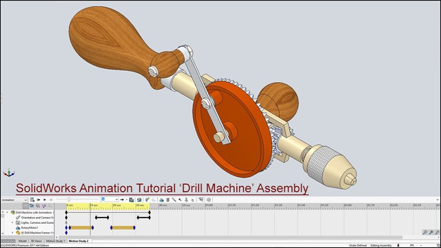
Animation displayed in 'Drill Machine' Assembly--SolidWorks 2014 (with caption and audio narration)

SolidWorks Animation Tutorial ‘Drill Machine’ Assembly_1

SolidWorks Animation Tutorial ‘Drill Machine’ Assembly_2

Serial No. 219

Animation displayed in 'Drill Machine' Assembly--SolidWorks 2014 (with caption and audio narration)

In this video, we will demonstrate how to  apply the different type of mates in the assembly environment for creating the animation.
..................................................................................
To watch full sketching video of this model 'Drill Machine', please visit my another associated video named as 'Drill Machine' (Video Tutorial) SolidWorks.

download-Link


Click the following link to get the model file: - http://bit.ly/2LMF9zg


Transcription of the Video

  1. Create a new assembly within an English template.
  2. The ‘Begin Assembly’ command is preactivated in the assembly design window.
  3. Go to the View tab, turn on the ‘Origins’ button.
  4. Place the ‘Drill Machine Frame’ in the assembly.
  5. Turn off the visibility of ‘Origins’ button.
  6. Save the file, call it as ‘Drill Machine with Animation’.
  7. Right-click on the design window and choose ‘New View’ tool in the Orientation dialogue box.
  8. Save the view as ‘Custom View’ in the Named View dialogue box and click OK.
  9. Activate the ‘Insert Components’ command and place the ‘Part9’ & ‘Part10’ file in the assembly.
  10. Rotate the ‘Part9’ file to the proper position by using ‘Move with Triad’ command.
  11. Apply a ‘Concentric’ mate between the selected inner cylindrical face of ‘Part9’ and outer cylindrical face of ‘Part10’.
  12. Choose ‘Lock Rotation’ option to stop the movement of the part, click OK to execute the command.
  13. Drag the ‘Part9’ file and apply ‘Coincident’ mate between the selected face of ‘Part10’ and selected inner circular face of ‘Part9’.
  14. Apply a ‘Concentric’ mate between the hole of ‘Part10’ and selected cylindrical face of ‘Drill Machine Frame’, which is highlighted in blue color.
  15. Choose ‘Lock Rotation’ option and click OK.
  16. Apply a ‘Coincident’ mate between the selected face of ‘Part9’ and selected face of ‘Drill Machine Frame’.
  17. Place the ‘Spindle’ in the assembly.
  18. Rotate the ‘Spindle’ in a proper position by using ‘Move with Triad’ command.
  19. Apply a ‘Concentric’ mate between the cylindrical face of ‘Spindle’ and the selected face of the hole of ‘Drill Machine Frame’.
  20. Drag the ‘Spindle’ and apply ‘Coincident’ mate between the selected face of ‘Spindle’ and selected face of ‘Drill Machine Frame’.
  21. Place the ‘Partr1’ file in the assembly.
  22. Apply a ‘Concentric’ mate between the cylindrical face of ‘Part1’ and cylindrical face of ‘Spindle’.
  23. Apply a ‘Coincident’ mate between the selected face of ‘Spindle’ and inner circular face of ‘Part1’.
  24. Apply another ‘Coincident’ mate between the Top Plane of ‘Spindle’ and Front Plane of ‘Part1’.
  25. Drag the chuck of a drill, you can observe here it is moving with the spindle.
  26. Save the assembly.
  27. Place the ‘Part2’ file in the assembly.
  28. Select the ‘Part2’ file from the Model Tree and drag two more copies of ‘Part2’ in the design window.
  29. Go to the View tab, turn on the ‘Temporary Axes’ button.
  30. The centre axis is visible in the assembly design window.
  31. Select the three copies of ‘Part2’ and rotate it.
  32. Apply a ‘Coincident’ mate between the ‘Axis1’ of first copy of ‘Part2’ and ‘Axis1’ of second copy of ‘Part2’.
  33. Next, apply a ‘Coincident’ mate between their slant edges.
  34. In the same way, apply a ‘Coincident’ mate between the second copy of ‘Part2’ and third copy of ‘Part2’.
  35. At the last, apply a ‘Coincident’ mate between their selected faces of ‘Part2’ files.
  36. Select all the components and rotate it.
  37. Apply a ‘Coincident’ mate between the Axis1 of ‘Part2’ and centre axis of the assembly.
  38. Apply a ‘Coincident’ mate between the inside circular face of ‘Part1’ and selected face of ‘Part2’.
  39. Turn off the ‘Temporary Axes’ button.
  40. Drag the ‘Part2’ file to examine the mate.
  41. Now see, the ‘Part2’ is moving on its own axis, so we will attach the planes of ‘Part1’ & ‘Part2’ by using ‘Coincident’ mate command.
  42. Select the Right Plane of ‘Part2’ and Front Plane of ‘Part1’ and activate the ‘Mate’ command.
  43. Click OK to execute the command.
  44. Now drag the ‘Part1’ to see the result.
  45. ‘Part1’, ‘Part2’ & Spindle of drill machine, each are rotating simultaneously.
  46. Save the assembly.
  47. Place the ‘Pinion-1’ in the assembly.
  48. Rotate the ‘Pinion-1’ in a suitable position by using ‘Move with Triad’ command.
  49. Apply a ‘Concentric’ mate between the center hole of ‘Pinion-1’ and selected cylindrical face of ‘Drill Machine Frame’.
  50. Place the ‘Pinion-2’ in the assembly.
  51. Apply another ‘Concentric’ mate between the center hole of ‘Pinion-2’ and cylindrical face of ‘Spindle.
  52. Apply a ‘Concentric’ mate between the side hole of the ‘Pinion-2’ and hole of ‘Spindle’.
  53. Place the ‘Revit’ in the assembly and fix it with the ‘Pinion’ by using ‘Mate’ command.
  54. Now drag the Pinion to examine the result.
  55. Place the ‘Bevel Gear’ & ‘Part7’ in the assembly.
  56. Rotate the ‘Bevel Gear’ & ‘Part7’ models in a desired position by using ‘Move with Triad’ command.
  57. Apply a ‘Concentric’ mate between the inner cylindrical face of ‘Bevel Gear’ & outer cylindrical face of ‘Part7’.
  58. Choose ‘Lock Rotation’ option and click OK to finish the command.
  59. Apply a ‘Coincident’ mate between the selected face of ‘Part7’ & selected face of ‘Bevel Gear’.
  60. Apply a ‘Concentric’ mate between the hole of ‘Part7’ & selected cylindrical face of ‘Drill Machine Frame’.
  61. Select the ‘Pinion-1’ & ‘Pinion-2’ from the model tree, right-click and choose ‘Isolate’ option.
  62. Go to the View tab, switch on the ‘Points’ button.
  63. The two points of ‘Pinion-1’ & ‘Pinion-2’ are visible in the design window.
  64. Whose names are ‘Intersection’ points, these points are also called as Vertices.
  65. Drag the Pinion-1 and activate the ‘Mate’ command, select intersection points of ‘Pinion-2’ & ‘Pinion-1’.
  66. And apply a ‘Coincident’ mate, disable the ‘Exit Isolate’ button.
  67. Drag the ‘Part7’ and switch-on the ‘Temporary Axes’ button.
  68. Apply a ‘Coincident’ mate between the Intersection point of ‘Bevel Gear’ and center axis of the assembly.
  69. Switch-off the ‘Points’ & ‘Temporary Axes’ button.
  70. Select the ‘Pinion-1’, ‘Pinion-2’ & ‘Bevel Gear’ part files from the model tree, right-click and choose ‘Isolate’ option.
  71. Activate the ‘Mate’ command, go to the ‘Mechanical Mates’ tab in the Mate dialogue box.
  72. Different types of mechanical mates are available here, choose any mate as you need according to your design.
  73. Choose the ‘Gear’ mate button, select the cylindrical face of ‘Pinion2’ and select the cylindrical face of ‘Bevel Gear’, this will be notified in the ‘Mate Selections’ area.
  74. In the ‘Ratio’ area, set the value 15:56 inch and click OK to finish the command.
  75. In the same manner, apply another gear mate between second pinion and bevel gear.
  76. Disable the ‘Exit Isolate’ button.
  77. Place the ‘Part4’ and ‘Washer’ in the assembly.
  78. Apply a ‘Concentric’ mate between the hole of ‘Part7’ and hole of ‘Washer’.
  79. Apply a ‘Coincident’ mate between the selected face of ‘Part7’ & selected face of ‘Washer’ which is highlighted in blue color.
  80. Apply a ‘Concentric’ mate between the hole of ‘Part4’ and selected cylindrical face of ‘Drill Machine Frame’.
  81. Apply a ‘Coincident’ mate between the selected circular face of ‘Drill Machine Frame’ and selected face of ‘Part4’.
  82. Apply a ‘Concentric’ mate between the hole of ‘Washer’ and hole of ‘Part4’.
  83. Now we will place ‘ANSI Inch Machine Screw Bolt’ in the assembly from the SolidWorks ‘Design Library’.
  84. Go to the ‘Task Pane’ tab and select the ‘Design Library’ button, expand the Toolbox icon and now see different kinds of ‘component standards’ are available here.
  85. Click ANSI Inch standard then click ‘Bolts and Screws’ folder.
  86. Next, click the Machine Screws folder and select ‘Pan Slot Head’ item.
  87. Drag the bolt in graphics area of the assembly as shown.
  88. Drop the bolt into the hole of ‘Part4’ in the following way.
  89. Select #10-24inch from the Size area and click OK to accept it.
  90. Select the ‘pan slot head’ bolt, right-click and choose ‘Edit Toolbox component’ option.
  91. Change the length value of the bolt 0.5 inch and click OK.
  92. Place the ‘Part3’ and ‘Part5’ file in the assembly.
  93. Apply a ‘Concentric’ mate between the selected circular face of ‘Part5’ & hole of ‘Part3’.
  94. Choose Lock Rotation option and click OK to finish the command.
  95. Apply a ‘Coincident’ mate between the selected circular face of ‘Part3’ and selected circular face of ‘Part5’.
  96. Apply a ‘Concentric’ mate between the hole of ‘Part4’ and outer cylindrical face of ‘Part3’.
  97. Apply a ‘Coincident’ mate between the selected face of ‘Part4’ and selected face of ‘Part3’.
  98. Bring another ‘Pan Slot Head’ bolt from the design library and insert it on the handle of drill machine as narrated in the earlier section.
  99. Change the length of the bolt as per our requirement and click OK.
  100. Insert the ‘Machine Screw Nut Hex’ in the assembly design window.
  101. Fix the hex nut on the bolt of the handle by using ‘Mate’ command.
  102. Save the assembly.
  103. Place the ‘Part6’ and ‘Part8’ files in the assembly by using ‘Insert Components’ command.
  104. Rotate the ‘Part6’ in the desired position by using ‘Move with Triad’ command.
  105. Apply a ‘Concentric’ mate between the outer cylindrical face of ‘Part8’ & outer cylindrical face of ‘Part6’.
  106. Apply a ‘Coincident’ mate between the selected circular face of ‘Part8’ and selected circular face of ‘Part6’.
  107. Apply a ‘Concentric’ mate between the selected cylindrical face of ‘Drill Machine Frame’ & selected circular face of ‘Part8’.
  108. Choose ‘Lock Rotation’ option and click OK to finish the command.
  109. Apply a ‘Coincident’ mate between the selected face of ‘Drill Machine Frame’ & selected face of ‘Part8’.
  110. Drag the handle of drill machine to examine the result, when the Bevel Gear rotates in an anti-clockwise direction then the Pinion of the drill machine rotates in a clockwise direction.
  111. Now we will do some alterations in the two ‘Gear’ mates.
  112. Go to the ‘Mates’ folder, select the ‘GearMate2’, right-click and choose ‘Edit feature’ option.
  113. Activate the ‘Reverse’ button and click OK.
  114. In the same manner, edit the ‘GearMate1’.
  115. Rotate the handle of drill machine to see the action.
  116. Apply a ‘Coincident’ mate between the Top Plane of ‘Part4’ & Right Plane of assembly.
  117. Suppress the ‘Parellel1’ mate.
  118. Activate the ‘New Motion Study’ command and expand the animation timeline.
  119. Activate the ‘Motor’ button in the animation timeline and rotate the model by using View Cube.
  120. In the Component/Direction section, Motion Location option is preactive in the Motor dialogue box.
  121. Select the cylindrical face of Bevel Gear as shown and set the value 6 RPM in the motion area.
  122. Click OK to execute the command.
  123. ‘Rotary Motor1’ key has added to the animation timeline at 0 second.
  124. Move the timebar at 1.5 second, right-click on the animation timeline and choose ‘Place Key’ option.
  125. Switch-off the ‘Rotary Motor1’ key at 0 second.
  126. Pause the motor for 1.5 second before the start of the animation.
  127. Move the timebar at 11.5 second and place a new key.
  128. Add another key at 19.5 second on the animation timeline.
  129. Switch-off the ‘Rotary Motor1’ key at 11.5 second.
  130. Move the timebar at 29.5 second and place one more key.
  131. Minimize the animation timeline and set the position of the model as shown.
  132. Choose ‘New View’ button from the ‘Orientation’ dialogue box.
  133. A ‘Named View’ dialogue box will be visible in the design window and change its name as ‘View-1’ and click OK.
  134. In the same manner, rotate the model in opposite direction and save it as ‘View-2’.
  135. Expand the animation timeline, go to the ‘Orientation and Camera’ tab and select the ‘Custom’ view key.
  136. Go to the View Cube and set ‘View-1’ from the view list.
  137. Select the ‘Custom’ view key, right-click and choose ‘Replace Key’ option.
  138. Now the Orientation and Camera key is replaced by change from the ‘Custom’ view to ‘View1’ with the aid of ‘Replace Key’ command.
  139. Move the time bar at 13 second and place a new key.
  140. Add a new key once again at 18 second, go to the View Cube and set ‘View-2’ from the view list.
  141. Time consume 5 seconds from changing ‘View-1’ to ‘View-2’ position.
  142. In the same way, add two more view keys at 31 & 36 seconds on the animation timebar.
  143. Select ‘Rotary Motor1’ key, right-click and choose ‘Off’ option.
  144. Click ‘Calculate’ button to check the motion study.
  145. Finally, click ‘Play from Start’ button to watch the full animation.
  146. Exit from the motion study environment and return back to assembly.
  147. Save the assembly.

Thursday, February 2, 2017

Drill Machine with Animation (Solid Edge ST9 Tutorial)

Drill Machine with Animation_1

Drill Machine with Animation_2

Serial No. 26

Drill Machine with Animation (Solid Edge ST9 Tutorial)

In this video we will describe you how to animate the assembly of ‘Drill Machine’ with the one bevel gear and two pinion by using ‘Rotational Motor’ command. It is assembly modeling tutorial. This assembly consist 1 Assembly and 22 part files (Drill Machine frame (Multi Body part) Spindle, Drill chuck, Gear, Pinion, Gear hub, Washer, Handle etc.) that are positioned according to design intent by using Assembly Constraints. This tutorial will give you a good practice of applying constraints in an assembly and give you an idea of Drill Machine mechanism.

It will cover the following topics.

........................................................................................................

• How to set the motor command between gear and pinion.

• Use assembly commands such as Flash Fit, Axial Align mate, Connect mate, Mate/Planar Align command etc.

• How to mate the parts by using ‘Flash Fit’ command in the assembly.

• How to mating between the vertex point of gear and pinion by using ‘Connect Mate’ command.

• How to create gear relationship between gear and pinion by using ‘Gear’ mate command and how to define the number of teeth of the gear and pinion (15/56) to define the gear interaction.

• How to lock the rotation of the component by using ‘Lock Rotation’ option in ‘Flash Fit’ command in the assembly.

• How to flip the component by using ‘Flip Side’ option in ‘Flash Fit’ command in the assembly.

• How to rotate and moving part by using ‘Drag Component’ command.

• How to insert component into the assembly using drag and drop from parts library by using ‘Insert Component’ command.

• Use ‘Show/Hide Component’ option in the assembly to mate the components more easily.

• How to hide all components except the selected components by using ‘Isolate’ command in the assembly.


download-Link


Click the following link to get the model file: - http://bit.ly/2MpDxKR

Saturday, January 21, 2017

Drill Machine (Volume-1)—Solid Edge ST9 Tutorial

Drill Machine_1

Drill Machine_2

Serial No. 23-A.

Drill Machine (Volume-1)—Solid Edge ST9 Tutorial

(Rest of the design of the model is completed in Volume-2)

In this Solid Edge Tutorial we will describe how to build the model ‘Drill Machine’. It is a Part and Assembly modelling tutorial. This assembly consist 1 Assembly and 22 part files (Drill Machine frame (Multi Body part) Spindle, Drill chuck, Gear, Pinion, Gear hub, Washer, Handle etc.) that are positioned according to design intent by using Assembly Constraints. This tutorial will give you a good practice of applying constraints in an assembly and give you an idea of Drill Machine mechanism.

How to construct the part ‘Drill Machine Frame’ (Multi body part). After creating the frame convert all multi body parts into a single solid body with the help of ‘Union’ command.

It will cover the following topics.

........................................................................................................

• Creating 2D Sketches on different Planes.

• Use the sketch constraints that are applied on during sketch creation.

• Use features command such as Revolved, Extrude, Cut, Subtract, Intersection, Union, Add Body, Normal Cutout, Helical Cutout etc.

• Use the ‘Add Body’ command to create multiple bodies in a single part file (‘Drill Machine Frame’).

• Use the ‘Revolve’ command with different options.

• How to create a realistic thread in our model Spindle and Part1 (UNF Screw External &Internal Thread Profile) by sweeping a cross section along a helical path by using ‘Helical Cutout’ command.

• How to apply knurl image on the face of the model with the help of ‘Styles’ tool.

• How to change the color of the model by using ‘Part Painter’ tool.

• Use assembly commands such as Flash Fit, Axial Align mate, Connect mate, Mate/Planar Align command etc.

• How to mate the parts by using ‘Flash Fit’ command in the assembly.

• How to mating between the vertex point of gear and pinion by using ‘Connect Mate’ command.

• How to create gear relationship between gear and pinion by using ‘Gear’ mate command and how to define the number of teeth of the gear and pinion (15/56) to define the gear interaction.

• How to lock the rotation of the component by using ‘Lock Rotation’ option in ‘Flash Fit’ command in the assembly.

• How to flip the component by using ‘Flip Side’ option in ‘Flash Fit’ command in the assembly.

• How to rotate and moving part by using ‘Drag Component’ command.

• How to insert component into the assembly using drag and drop from parts library by using ‘Insert Component’ command.

• Use ‘Show/Hide Component’ option in the assembly to mate the components more easily.

• How to hide all components except the selected components by using ‘Isolate’ command in the assembly.


download-Link


Click the following link to get the model file: - http://bit.ly/2LWL8BP

Drill Machine (Volume-2)—Solid Edge ST9 Tutorial

Drill Machine_1

Drill Machine_2

Serial No. 23-B.

Drill Machine (Volume-2)—Solid Edge ST9 Tutorial

(Starting design of the model is created in Volume -1)

In this Solid Edge Tutorial we will describe how to build the model ‘Drill Machine’. It is a Part and Assembly modelling tutorial. This assembly consist 1 Assembly and 22 part files (Drill Machine frame (Multi Body part) Spindle, Drill chuck, Gear, Pinion, Gear hub, Washer, Handle etc.) that are positioned according to design intent by using Assembly Constraints. This tutorial will give you a good practice of applying constraints in an assembly and give you an idea of Drill Machine mechanism.

How to construct the part ‘Drill Machine Frame’ (Multi body part). After creating the frame convert all multi body parts into a single solid body with the help of ‘Union’ command.

It will cover the following topics.

........................................................................................................

• Creating 2D Sketches on different Planes.

• Use the sketch constraints that are applied on during sketch creation.

• Use features command such as Revolved, Extrude, Cut, Subtract, Intersection, Union, Add Body, Normal Cutout, Helical Cutout etc.

• Use the ‘Add Body’ command to create multiple bodies in a single part file (‘Drill Machine Frame’).

• Use the ‘Revolve’ command with different options.

• How to create a realistic thread in our model Spindle and Part1 (UNF Screw External &Internal Thread Profile) by sweeping a cross section along a helical path by using ‘Helical Cutout’ command.

• How to apply knurl image on the face of the model with the help of ‘Styles’ tool.

• How to change the color of the model by using ‘Part Painter’ tool.

• Use assembly commands such as Flash Fit, Axial Align mate, Connect mate, Mate/Planar Align command etc.

• How to mate the parts by using ‘Flash Fit’ command in the assembly.

• How to mating between the vertex point of gear and pinion by using ‘Connect Mate’ command.

• How to create gear relationship between gear and pinion by using ‘Gear’ mate command and how to define the number of teeth of the gear and pinion (15/56) to define the gear interaction.

• How to lock the rotation of the component by using ‘Lock Rotation’ option in ‘Flash Fit’ command in the assembly.

• How to flip the component by using ‘Flip Side’ option in ‘Flash Fit’ command in the assembly.

• How to rotate and moving part by using ‘Drag Component’ command.

• How to insert component into the assembly using drag and drop from parts library by using ‘Insert Component’ command.

• Use ‘Show/Hide Component’ option in the assembly to mate the components more easily.

• How to hide all components except the selected components by using ‘Isolate’ command in the assembly.


download-Link


Click the following link to get the model file: - http://bit.ly/2LWL8BP

Monday, April 25, 2016

Drill Machine - Motion Simulation (Video Tutorial) Siemens NX 10

Drill Machine_1

Drill Machine_2


Serial No. 16.

Drill Machine - Motion Simulation (Video Tutorial) Siemens NX 10


In this video we will describe, how to simulate the assembly of ‘Drill Machine’ with different joints, Gear joint, Revolute joint and so on in Motion Simulation Application Environment.

 
download-Link

Click the following link to get the model file: - http://bit.ly/2nmTWY5

Wednesday, October 15, 2014

Drill Machine (Volume-2) SolidWorks 2014 Tutorial


Serial No. 25-B


Drill Machine (Volume-2) SolidWorks 2014 Tutorial 


This Solidworks Assembly tutorial which also covers topics from Solidworks Basics like sketching and part modelling, displays a creation process of an assembly named ‘Drill Machine’.
After modelling it we will be able to create animation of the model .But these things are not displayed in the same video, to know this you will have to watch the related video tutorial. The links are mentioned below.
The model contains 17 part which consists Tool Box parts also. First we create the base frame then later each component is created individually with no relation to each other which you can term Bottom-up designing process. In this process first parts are designed individually then inserted into the assembly and setup by using the mates. When the parts are modified the changes also appear in the assembly.
It means by watching it, lots of solidworks learning can be achieved… the video is quite long so it is split into two parts.
.....................................................
3D Solid Modelling Videos: Drill Machine (Volume-1) Video Tutorial--SolidWorks 2014

3D Solid Modelling Videos: Drill Machine (Volume-2) Video Tutorial--SolidWorks 2014
......................................................
To learn the animation of the model visit the following link:--
3D Solid Modelling Videos: Animation by Precise Positioning Display in Drill Machine (SolidWorks 2014)

If you want to get the newer version of this video, we have uploaded this video with audio narration only One Volume on our YouTube channel.  Please you can watch this video so that you can understand it easily.


download-Link

Click the following link to get the model file: - http://bit.ly/2oo6cI8


....................................................................................
Visit the following link to watch the basic tutorial on SolidWorks by us
https://www.youtube.com/playlist?list=PLb-IhKRMYSES3Zw3QHmQVqQ-rcFVzgYHy
.........................................................................
To watch more detailed tutorials on the same software visit the following link
https://www.youtube.com/playlist?list=PLKWX3xUP3pPo77gFCyy669sI76qJa5jKw
...................................................................................
Hope all of you enjoyed the tutorial. If you find the video useful please like it and share it with your friends/colleagues and do not forget to subscribe us to get latest updates about our new uploads.
http://www.youtube.com/user/nisheethsorjm?sub_confirmation=1
....................................................................................................
Dear Viewers if you like our work and wanted to support us, to keep continuing the good work, then become a patron of ours at ‘Patreon’ site. Patreon is a simple way for you to contribute to the creator’s work every month/ every time they release their new work and get rewards in return. Please visit the following link to know all about our work and what we are offering a reward to our patrons…
https://www.patreon.com/nisheethsri
...........................................................................................................................……………………………

Drill Machine (Volume-1) SolidWorks 2014 Tutorial


Serial No. 25-A

Drill Machine (Volume-1) SolidWorks 2014 Tutorial 

This Solidworks Assembly tutorial which also covers topics from Solidworks Basics like sketching and part modelling, displays a creation process of an assembly named ‘Drill Machine’.
After modelling it we will be able to create animation of the model .But these things are not displayed in the same video, to know this you will have to watch the related video tutorial. The links are mentioned below.
The model contains 17 part which consists Tool Box parts also. First we create the base frame then later each component is created individually with no relation to each other which you can term Bottom-up designing process. In this process first parts are designed individually then inserted into the assembly and setup by using the mates. When the parts are modified the changes also appear in the assembly.
It means by watching it, lots of solidworks learning can be achieved… the video is quite long so it is split into two parts.
.....................................................
3D Solid Modelling Videos: Drill Machine (Volume-1) Video Tutorial--SolidWorks 2014

3D Solid Modelling Videos: Drill Machine (Volume-2) Video Tutorial--SolidWorks 2014

If you want to get the newer version of this video, we have uploaded this video with audio narration only One Volume on our YouTube channel.  Please you can watch this video so that you can understand it easily.

To learn the animation of the model visit the following link:--
3D Solid Modelling Videos: Animation by Precise Positioning Display in Drill Machine (SolidWorks 2014)


download-Link

Click the following link to get the model file: - http://bit.ly/2oo6cI8


....................................................................................
Visit the following link to watch the basic tutorial on SolidWorks by us
https://www.youtube.com/playlist?list=PLb-IhKRMYSES3Zw3QHmQVqQ-rcFVzgYHy
.........................................................................
To watch more detailed tutorials on the same software visit the following link
https://www.youtube.com/playlist?list=PLKWX3xUP3pPo77gFCyy669sI76qJa5jKw
...................................................................................
Hope all of you enjoyed the tutorial. If you find the video useful please like it and share it with your friends/colleagues and do not forget to subscribe us to get latest updates about our new uploads.
http://www.youtube.com/user/nisheethsorjm?sub_confirmation=1
....................................................................................................
Dear Viewers if you like our work and wanted to support us, to keep continuing the good work, then become a patron of ours at ‘Patreon’ site. Patreon is a simple way for you to contribute to the creator’s work every month/ every time they release their new work and get rewards in return. Please visit the following link to know all about our work and what we are offering a reward to our patrons…
https://www.patreon.com/nisheethsri
...................................................................................................................................

Sunday, December 8, 2013

Drill Machine-Dynamic Simulation-Autodesk Inventor 2012 (with caption and audio narration)


Drill Machine-Dynamic Simulation_1


Drill Machine-Dynamic Simulation_2  


Serial No. 30

Drill Machine-Dynamic Simulation-Autodesk Inventor 2012 (with caption and audio narration)

In this video, we will demonstrate how to apply the different type of mates in the assembly environment for creating the Dynamic Simulation of the ‘Drill Machine’.


download-Link 


Click the following link to get the model file: -http://bit.ly/2ncLp9z


Transcription of Video

Display of Motion in Drill Machine through Dynamic Simulation

  1. Create a New ‘Standard (in).iam’ Assembly and save it with the name ‘Drill Machine-Dynamic Simulation’.
  2. Select Place component from the marking menu and place the Frame in the Assembly.
  3. Place Handle-1 and Handle Cap-1 in the Assembly.
  4. Start the Constrain Command and choose Insert Mate from the type option.
  5. First select the inner circular edge of Handle Cap, then select outer circular edge of Handle and click Ok.
  6. Give another Insert Mate between Inner edge of Handle Cap and circular edge of Frame as displayed.
  7. Re-orient the design window using View Cube.
  8. Set the current view as Home View using the toggle next to View Cube.
  9. Place Gear Wheel and Gear in the Assembly.
  10. Apply a Mate Constraint between Axis of Gear Wheel and Axis of Gear.
  11. Next, apply a Mate Constraint between face of Gear Wheel and face of Gear.
  12. Apply another Mate Constraint between YZ Plane of Gear Wheel and XZ Plane of Gear.
  13. Re-orient the Gear Wheel with respect to Frame using Rotate Component Tool.
  14. Apply an Axis Mate between Gear Wheel and stud of Frame.
  15. Place Spindle in the Assembly.
  16. Apply a Mate Constraint between Axis of Frame and Axis of Spindle.
  17. Next, apply a Mate Constraint between inner face of supporting cylinder of frame and back face of the spindle.
  18. Place Pinion-2 in the Assembly.
  19. Apply a Mate Constraint between Axis of Pinion-2 and Axis of Spindle.
  20. Apply an Axis Mate between hole on Pinion-2 and hole on Spindle.
  21. Place Locking Pin in the Assembly and fix it inside the hole of Pinion using Insert Mate.
  22. Place Pinion-1 in the Assembly.
  23. Align the Pinion-1 to match it with the Frame.
  24. Apply a Mate Constraint between Axis of Frame and Axis of Pinion-1.
  25. Select Pinion-1, Pinion-2 and Gear, then right click in the design window, choose ‘Isolate’ from the context menu.
  26. Set the Browser from Assembly view to Modeling View.
  27. Locate the Intersection Point of Pinion-2 inside the Browser Bar.
  28. Apply a Mate Constraint between the Intersection Point of Pinion-2 and Intersection Point of Gear.
  29. In the same manner, apply a Mate Constraint between the Intersection Point of Pinion-2 and the Intersection Point of Pinion-1.
  30. Activate Motion Constraint; first select the Axis of Pinion-1 and afterward the Axis of Gear.
  31. Enter the value 15/56 in the Ratio Input box and click Apply.
  32. Apply same step as above to give motion constraint between Pinion-2 and Gear.
  33. Right click in the design window, choose Undo Isolate from the context menu.
  34. Place Chuck in the Assembly.
  35. Apply a Mate Constraint between the Axis of Spindle and the Axis of Chuck.
  36. Place a Mate Constraint between inner circular face of Chuck and front face of Spindle.
  37. Place another Mate Constraint between YZ Plane of Chuck and YZ Plane of Spindle.
  38. Place Three instances of Jaw in the Assembly.
  39. Apply an Axis Mate between two subsequent Jaws.
  40. Next, apply a Mate between their edges.
  41. Apply a Flush Mate between their end faces.
  42. In the same manner, constraint the third Jaw.
  43. Apply a Mate Constraint between inner circular face of Chuck and rear face of Jaw.
  44. Apply a Mate Constraint between the Axis of Chuck and the Axis of Jaw.
  45. Place a Mate Constraint between YZ Plane of Chuck and YZ Plane of any one Jaw.
  46. Place Handle-2 and Handle Cap-2 in the Assembly.
  47. Apply an Insert Mate between inner circular edge of Handle Cap-2 and outer circular edge of Handle-2.
  48. Position the Handle Cap-2 in respect of the stud of Frame by using Rotate Component Tool.
  49. Apply an Insert Mate between front circular edge of Handle Cap-2 and inner circular edge of stud.
  50. Place Handle Connecting Plate in the Assembly.
  51. Apply an Insert Mate between edge of the hole on Handle Connecting Plate and inner circular edge of stud.
  52. Place Washer-1 in the Assembly.
  53. Apply an Insert Mate between edge of the hole on Washer-1 and edge of the hole on Gear Wheel.
  54. Apply a Mate Constraint between YZ Plane of Handle Connecting Plate and Axis of the hole on Gear Wheel.
  55. Place Screw-2 in the Assembly.
  56. Apply an Insert Mate between inner circular edge of Screw-2 and edge of the hole on Handle Connecting Plate.
  57. Place Handle-3 and Handle Cap-3 in the Assembly.
  58. Fit the Handle Cap-3 over the Handle-3 with the help of Insert Mate.
  59. Apply another Insert Mate between the Handle Cap-3 and hole on the Handle Connecting Plate.
  60. Place Screw-1 and Nut in the Assembly.
  61. Fix the Screw-1 on the Handle-3 with the help of Insert Mate.
  62. Fix the Nut on the Screw-1 by applying Insert Mate.
  63. Open the Visibility of surfaces named ‘Pitch Diameter’ of Pinion-2, Pinion-1 and Gear.
  64. ‘Isolate’ the Pinion-1, Pinion-2 and Gear in the Assembly.
  65. Activate the Dynamic Simulation Tool from the Begin Panel of Environments Tab.
  66. Select Insert Joint in the Marking menu.
  67. Select ‘Rolling: Cone on Cone’ from the drop down menu of Insert Joint dialog box.
  68. Select Pitch Diameter of Pinion-2 in ‘Component 1’ option and select Pitch diameter of Gear in ‘Component 2’ option and click Apply.
  69. In the same manner select Pitch Diameter of Pinion-1 and select Pitch diameter of Gear and click Ok.
  70. Finish Dynamic Simulation and return to Assembly Modelling environment.
  71. Close the visibility of surfaces named ‘Pitch Diameter’ of Pinion-1, Pinion-2 and Gear.
  72. Right Click in the design window and click ‘Undo Isolate’ option.
  73. Activate Dynamic Simulation Tool.
  74. Select Revolution:2 joint in the Browser under the Standard Joints folder, right click and select Properties from the context menu.
  75. Click dof 1 (R) tab and select Edit imposed motion button and check the Enable imposed motion option.
  76. Click the arrow to expand the input choices, and click Constant Value.
  77. Enter the value 360 deg/s and click Ok.
  78. In Simulation Player, fill the value 1000 in the Images field area.
  79. Clear the screen by activating the Clean Screen command.
  80. Click Run in the Simulation Player to display motion in Drill Machine.

Monday, April 25, 2011

Drill Machine (Autodesk Inventor 2010 Tutorial)


Serial No. 29

Drill Machine (Video Tutorial) Autodesk Inventor 2010

This Autodesk Inventor Part & Assembly modelling tutorial which also covers topics from Inventor Basics like sketching and part modelling display a creation process of an assembly named ‘Drill Machine’. After modelling it we will be able to create the animation of the model. But these things are not displayed in the same video, to know this you will have to watch the related video tutorial. The links are mentioned below. The model contains 16 part and 4 content centre part files which consists of a content centre library. First, we create the Drill Machine frame then later each component is created individually with no relation to each other which you can term Bottom-up designing process. In this process, first parts are designed individually then inserted into the assembly and setup by using the mate command. When the parts have modified the changes also appear in the assembly.
……………………………………………………………..
To learn the dynamic simulation of the model visit the following link:--
https://www.youtube.com/watch?v=jCyx4UqEGtY


download-Link 


Click the following link to get the model file: -  http://bit.ly/2mcIbTx


....................................................................................................
Visit the following link to watch the basic tutorial on Autodesk Inventor by us
https://www.youtube.com/playlist?list=PLb-IhKRMYSERYpB48aY-sZ10fN6CfXIL4
.........................................................................
To watch detailed tutorials on the same software visit the following link
https://www.youtube.com/playlist?list=PL74BDF7431ED13443
..........................................................................................
Hope all of you enjoyed the tutorial. If you find the video useful please like it and share it with your friends/colleagues and do not forget to subscribe us to get latest updates about our new uploads.
http://www.youtube.com/user/niveshandnisheeth?sub_confirmation=1
....................................................................................................
Dear Viewers if you like our work and wanted to support us, to keep continuing the good work, then become a patron of ours at ‘Patreon’ site. Patreon is a simple way for you to contribute to the creator’s work every month/ every time they release their new work and get rewards in return. Please visit the following link to know all about our work and what we are offering as the reward to our patrons…
https://www.patreon.com/nisheethsri+